 |
|||
|
|
|||
|
|
|||
| ||||||||||
|
|
 TM 5-4320-273-14
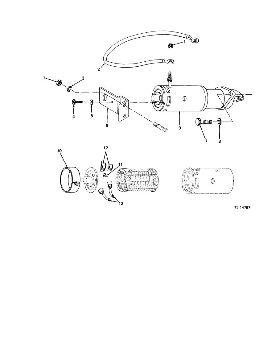
1. Nut
7. Capscrew
2. Cable
8. Lockwasher
3. Lockwasher
9. Starting motor
10. Cover band
4. Machine screw
11. Brush spring set
5. Flat washer
12. Brush set
6. Support bracket
Table 4-2. Troubleshooting -- Continued
MALFUNCTION
TEST OR INSPECTION
CORRECTIVE ACTION
ENGINE -- Continued
Remove the nuts (1) and lockwashers (3) that secure the support bracket (6) to the engine. Remove the
machine screw (4) and the flat washer (5) that mount the starting motor to the support bracket (6). Remove
the support bracket.
Remove the three capscrews (7) and lockwashers (8) that secure the starting motor (9) to the flywheel
housing.
Pull the starting motor straight out to remove from engine. Inspect starter Bendix for operation and starter
for worn brushes.
Replace brushes if they are worn more than 3/8 inch (0.95 cm) as follows:
Loosen cover band screw and slide the cover band (10) from the brush accees openings in the starter frame.
Unhook the spring set (11) retaining each brush and hold it out of the way of the brush. Holding the brush
set (12) by the leads carefully remove brush through the access opening. Remove brush only far enough to
disconnect brush leads from field leads. Repeat this procedure for each brush.
|
|
Privacy Statement - Press Release - Copyright Information. - Contact Us |
