 |
|||
|
|
|||
|
|
|||
| ||||||||||
|
|
 (14) Remove the oil seal (29).
and shim (26) with cap screws (23) and lock washers
(24). Tighten main bearing plate cap screws to 25 to 30
(15) Remove the crankshaft (30) and crankshaft
foot-pounds torque.
gear (31) by pulling them through the open end of the
(7) When you get the engine reassembled to
engine block.
(16) Remove the bearing retainer plate (36, fig.
this extent, check crankshaft end play with a dial indi-
3-13) from the flywheel end by removing the six cap
cater. The end play shall be 0.002 to 0.005 inch, engine
screws (34) and lock washers (35) that secure it to the
cold. If end play is not within limits, remove bearing
plate and add shim gaskets (27 and 28) as necessary.
engine block.
b. Cleaning and Inspection.
Gaskets come in thicknesses of 0.003 and 0.006 inch.
(8) Install the valve tappets (29, fig. 3-10) in
(1) Discard and replace all gaskets and seals.
(2) Clean all parts with cleaning solvent (fed.
the engine block.
spec. P-D-680); dry thoroughly. Clean oil passages in
(9) Mount the cylinder blocks on the engine
the crankshaft with a rifle cleaning brush. Make sure
block (para 3-16).
(10) Install the pistons and connecting rods
all passages are open.
(3) Inspect the crankshaft for cracks, worn or
scored journals, damaged threads, and burred key-
(11) Install the oil pump (para 3-14), oil filler
ways. Refer to table 3-1 for wear limits. If magnetic
(12) Install the idler gear and shaft (para 3-11).
particle inspection equipment is available, use it to
(13) Install the gear cover (para 3-10).
check the crankshaft for hidden flaws. Replace a dam-
(14) Install the governor assembly (para 3-9).
aged crankshaft.
(4) Inspect the crankshaft gear for cracked,
(15) Install the air shrouding Ipara 3-7).
(16) Install the carburetor and manifolds (TM
chipped, or broken teeth. If you have to replace a
5-4320-272-12).
damaged gear, use a gear puller to remove gear from
the crankshaft.
(17) Install the flywheel alternator (para 3-6).
(18) Install the flywheel assembly on the engine
(5) There is very little wear in the main bear-
ings so you should not remove the bearing cones (34,
(19) Install the oil filter to flywheel shrouding
necessary. If the bearings are damaged and must be
Ppare 3-4).
removed, use pullers to remove bearing cones and
press or drive out the cups.
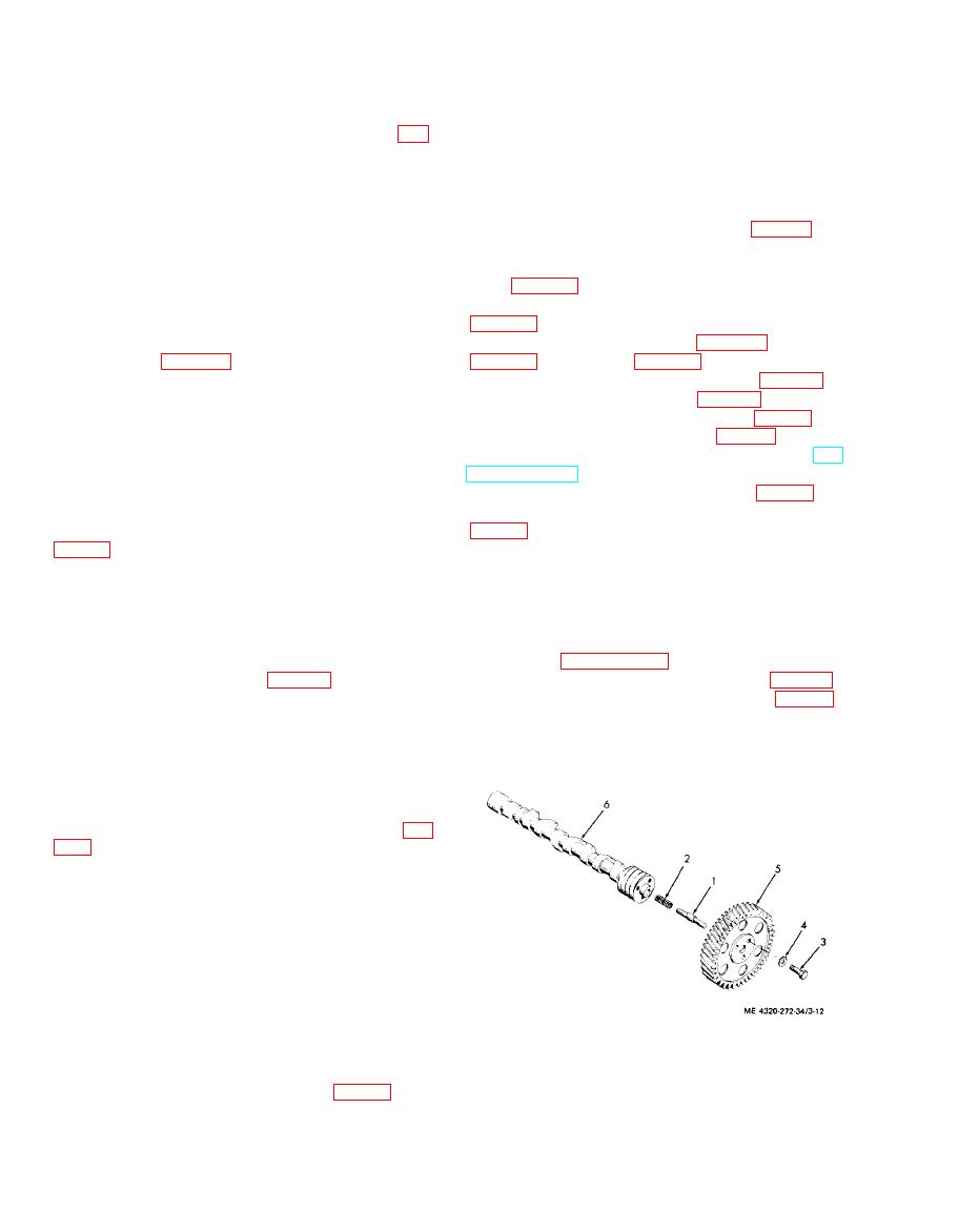
3-19. Camshaft
c. Installation.
a. Removal.
(1) Remove the main bearing and crankshaft
(1) If you had to remove the main bearings
as directed in paragraph 3-18 a.
because they were damaged, install new bearings by
pressing one bearing cup (33, fig. 3-11) into engine
(2) With all the valve tappets (19, fig. 3-10)
removed, you can withdraw the camshaft (6, fig. 3-12)
block and the other bearing cup into bearing retainer
plate (25). Carefully press bearing cones (34) onto
and gear (5) from the engine block.
crankshaft. You must make certain that bearing cups
and cones are seated squarely.
(2) Aline gear keyway to key (32) placed
in crankshaft keyway and press gear (31) on cran-
shaft (30).
(3) Install the bearing retainer plate (36, fig.
and lock washer (35).
(4) Lubricate the main bearings and crankpin
journals with a light coat of engine oil.
(5) Position the crankshaft assembly in the
engine block.
CAUTION
When installing the crankshaft, you must
make sure the timing marks on the
crankshaft gear are alined with the timing
marks on the camshaft gear.
1. Thrust plunger
4. Lockwasher
2. Spring
5. Gear
(6) You will notice the word TOP cast on the
6. Camshaft
outside of the bearing retainer plate (25, fig. 3-11); the
3. Screw
plate must be mounted in this position. Secure the
bearing retainer plate (25), new gaskets (27 and 28),
|
|
Privacy Statement - Press Release - Copyright Information. - Contact Us |
