 |
|||
|
|
|||
|
|
|||
| ||||||||||
|
|
 when you r e a s s e m b l e the valve. Tighten the
(2) To adjust the check valve for automatic
packing nut tightly enough to prevent leaking, but
closing, rotate the spring bracket (14) coun-
not so tightly that it prevents free rotation of the
terclockwise so that the spring pulls the check valve
shaft.
closed after you operate the lever manually to fully
( 2 ) Adjust the check valve for automatic
open the valve.
closing or for manual closing as directed in sub-
(3) To adjust the check valve so that it
paragraph a above.
remains open when set, rotate the spring bracket
(3) After you install the valve, start the pump
( 1 4 ) clockwise so that an overcentering action
and check that the valve opens and closes properly
o c c u r s as the valve is fully opened, requiring
and t h a t t h e r e a r e n o l e a k s . C o r r e c t a n y
manual pressure on the lever to close it.
deficiencies.
(4) After you have made the required ad-
justment, tighten the cap screws (10 and 11) to lock
4 - 4 5 . Air Eliminator
the spring bracket in position.
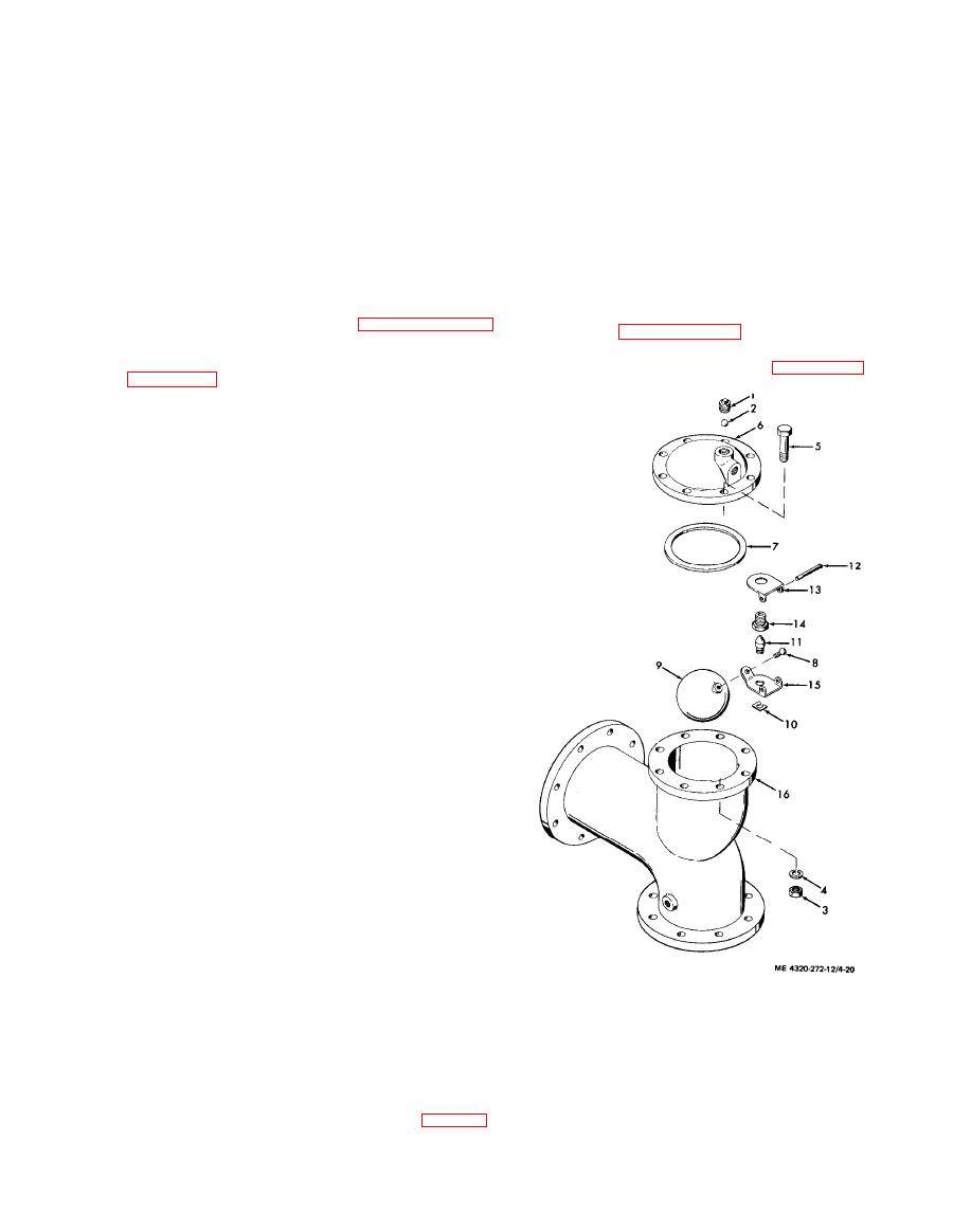
a. Removal and Disassembly. R e m o v e t h e a i r
b. Removal and Disassembly. R e m o v e t h e
eliminator from the discharge piping assembly as
check valve as indicated in paragraph 4-42.
described in paragraph 4-42. Disassemble the air
Disassemble the check valve following the sequence
eliminator following the sequence of index numbers
of index numbers assigned to the exploded view in
assigned to the exploded view in figure 4-20.
(1) To remove the valve shaft (21), you must
remove the setscrews (22) and the packing nut
(20), and insert a soft drift through the hole from
which the plug (19) was removed. Tap on the end
of the drift to dislodge the shaft.
(2) You will have to use a pointed or hooked
instrument to dislodge the packing rings (25) from
the body (28).
( 3 ) Do not remove the stud (27) from the
valve body (28) unless they are damaged or loose.
c. Cleaning and Inspection.
WARNING
Clean all parts in a well-ventilated area.
Avoid inhalation of solvent fumes and
prolonged exposure of the skin to
c l e a n i n g solvent. Wash exposed skin
thoroughly.
( 1 ) Discard and replace the packing rings
( 2 5 ) . Clean all remaining parts with cleaning
solvent (fed. spec. P-D-680); dry thoroughly.
( 2 ) Inspect the valve disc (8) for cracks,
distortion, or other damage. You can remove minor
burrs on the seating surface with fine emery cloth.
(3) Inspect valve body (28) for cracks,
damaged threads, damaged flanges, worn shaft
b o r e , and damaged seating surface. You can
remove minor nicks or burrs from the valve seats if
necessary. Clean up the seats evenly so that they
permit proper seating of the valve discs.
( 4 ) Inspect the shaft (21) for wear of the
bearing surfaces. Replace if you see any indications
of wear.
(5) Inspect all other parts for cracks,
distortion, a n d damaged threads; replace any
9. Float
1. Pipe plug
damaged parts.
10. Retainer
2. Ball
d. Reassembly and Installation. R e a s s e m b l y
11. Valve
3. Nut
and installation is essentially the reverse of the
12. Pin
4. Lock washer
disassembly and removal sequence. Refer to figure
13. Clip
5. Cap screw
4 - 1 9 and 4-17. Pay particular attention to the
14. Valve seat
6. Cover
7. Gasket
15. Lever
following:
8. Screw
16. Body
( 1 ) Use new packing rings (25, fig. 4-19)
view.
|
|
Privacy Statement - Press Release - Copyright Information. - Contact Us |
