 |
|||
|
|
|||
|
Page Title:
Section V. CAMSHAFT AND GOVERNOR |
|
||
| ||||||||||
|
|
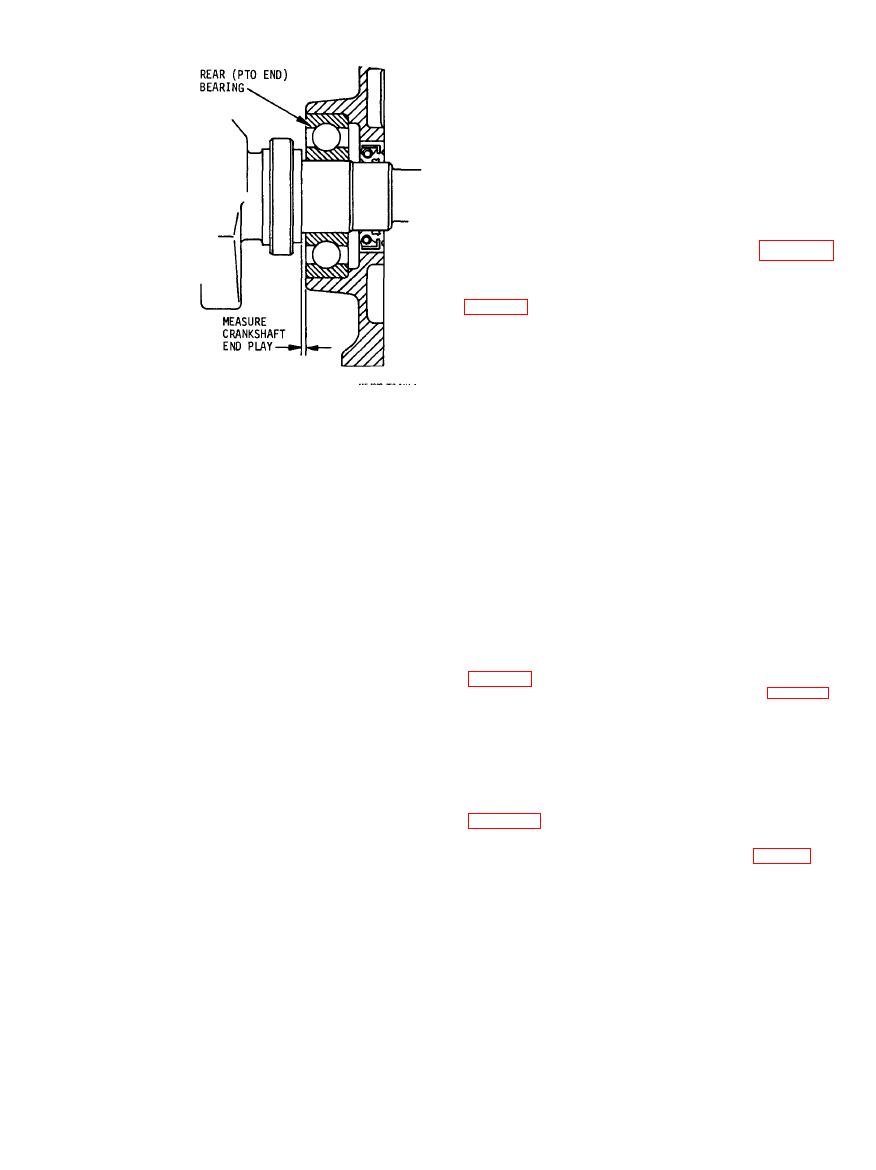 f. Check that the crankshaft rotates freely
without any binding or catching. Correct any
difficulties.
g. Lubricate the lips of the oil seals (8 and 11)
with grease. Slide the seals on the ends of the
crankshaft, taking care to prevent damage to the
sealing lips. Position the seals on the shaft so that
the lips face inward. Turn the engine on its side and
drive the seals squarely into the seats on the engine
cylinder block and on the bearing plate.
h. Install the magneto and flywheel (TM 5-
4320-259-12).
10).
j. Install the centrifugal pump on the engine
k. Install the carburetor, fuel tank and lines,
muffler, and air cleaner on the engine and service
the engine (TM 5-4320-259-12).
Section V. CAMSHAFT AND
GOVERNOR
cause the engine to slow down momentarily. This
4-15. Description
change will be sensed by the governor and a
a. The camshaft is gear driven by the geared
resulting adjustment of the carburetor throttle lever
portion of the crankshaft. It rotates in a 1:2 ratio
will restore the engine to the governed speed almost
with the crankshaft. The camshaft rides on a pin
immediately.
which extends through the cylinder block, parallel
4-16. Removal and Disassembly
with the crankshaft. The camshaft has one exhaust
a. Remove the air cleaner, muffler, fuel tank and
valve cam, one intake valve cam, and one breaker
lines, carburetor, and breaker points (TM 5-4320-
point cam. The valve cams operate the valve
159-12).
tappets to open and close the valves at the required
b. Remove the centrifugal pump from the engine
time of the engine cycle. The breaker point cam
engages the breaker point pin which operates the
c. Remove the cylinder head and valves (para 4-
ignition breaker point.
4).
b. The governor is driven by the camshaft to
d. Remove the piston and connecting rod (para
maintain control of the engine speed. The governor
4-8 ).
is a flyball type in which a driver forces four captive
e. Remove the flywheel and magneto (TM 5-
steel balls to rotate. As the balls rotate, centrifugal
4320-259-12).
force throws them outward against a dished race.
This causes the dished race to move axially. The
axial movement of the race is transferred to an
g. Invert the cylinder block. Using a small
externally mounted lever through a cross shaft. The
punch, drive out the camshaft pin (13, fig. 4-7),
cross shaft extends through the wall of the crank-
applying pressure from the power takeoff side of
case and is perpendicular to the camshaft. The
the engine. After the pin clears the rear end of the
externally mounted lever is linked to the throttle
crankcase, it will slide out easily.
lever on the carburetor. As engine speed increases,
h. Lift the assembled camshaft and governor
the movement of the governor parts causes the
from the cylinder block.
throttle lever to close to decrease engine speed. As
i. Remove the valve tappets (20) from the
the engine speed decreases, the governor parts
cylinder block.
cause the throttle lever to open. In this manner, a
state of equilibrium is reached and the engine speed
remains constant. An increased engine load will
|
|
Privacy Statement - Press Release - Copyright Information. - Contact Us |
