 |
|||
|
|
|||
|
Page Title:
Section IV. MAIN BEARINGS AND CRANKSHAFT |
|
||
| ||||||||||
|
|
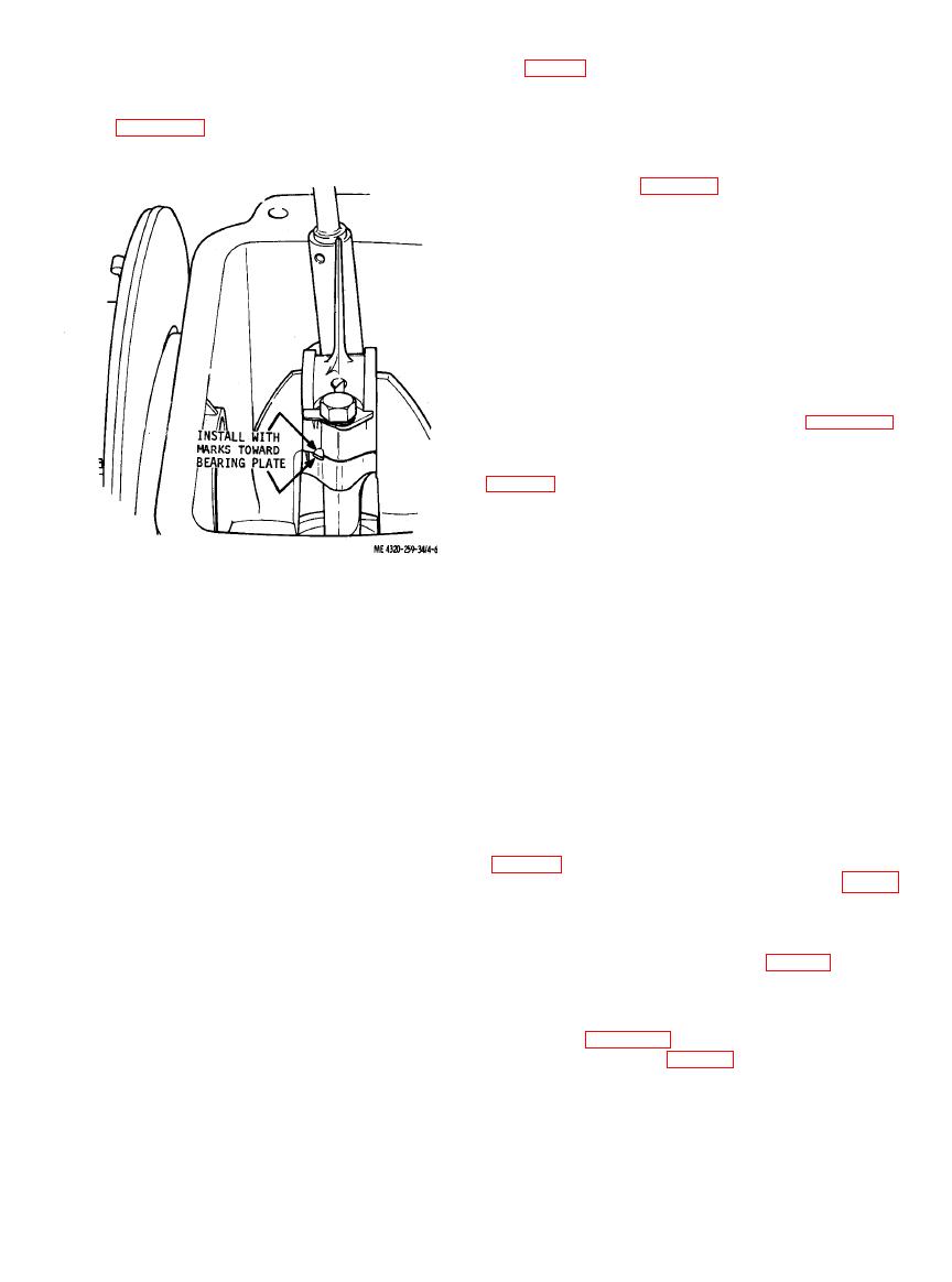 f. Temporarily install the connecting rod cap
e. When securing the connecting rod (28) and
(21, fig. 4-1) on the connecting rod and torque the
cap (21) in the crankshaft journal, check that the
cap screws (18) to 12 foot-pounds. Use plastigage
match marks on the parts are alined and that they
or other means of determining the running
are toward the bearing plate end of the engine.
clearance between the crankpin and the connecting
Refer to figure 4-6. Make sure the bearing journal
rod. Running clearance shall be 0.001 to 0.0025
is thoroughly lubricated.
inch. If running clearance is excessive, check the
dimensions given in table 4-1 to determine if the
crankshaft or the connecting rod must be replaced.
g. Secure the connecting rod cap (21) to the
connecting rod (28) with cap screws (18), flat
washers (19), and the lock (20). Torque the cap
screws to 12 foot-pounds. After tightening, bend
tangs of the lock against a flat of the screws to lock
them in place.
h. When installing the oil pan (16), be sure to
use a new gasket (17). Tighten the cap screws (15)
evenly and alternately to prevent gaps in the gasket
which could result in oil leaks.
6).
j. Install the centrifugal pump on the engine
marks.
Section IV. MAIN BEARINGS AND CRANKSHAFT
4-11. Description
piston assembled, minimizing vibration as the
crankshaft rotates. The toothed segment of the
at each end of the crankshaft. The bearing at the
crankshaft engages the camshaft gear to drive the
power takeoff end of the shaft is seated in the
crankshaft and governor.
bearing bore of the cylinder block. The bearing at
the flywheel end of the shaft is seated in a bearing
plate which is bolted to the cylinder block. Both
lines, and carburetor. (TM 5-4320-259-12).
bearings are lubricated by splash as the dipper on
b. Remove the centrifugal pump from the engine
the connecting rod cap dips into the engine oil in
the oil pan with each revolution of the crankshaft,
dispersing oil throughout the interior of the engine.
4-8).
b. Since both ends of the crankshaft extend from
d. Remove the flywheel and magneto (TM 5-
the crankcase, it is necessary to provide shaft seals
4320-259-12).
to prevent oil leakage around the shaft. These are
lip-type seals, one of which is pressed into the
washers (3), and flat washers (4) that secure the
cylinder block bore and the other into the bearing
bearing plate (5) to the cylinder block (23).
plate bore.
Remove the bearing plate. If necessary, use a puller
c. The crankshaft is counterbalanced to
as shown in figure 4-8 to remove the bearing plate.
counteract the weight of the connecting rod and
Remove the gasket (6, fig. 4-7).
|
|
Privacy Statement - Press Release - Copyright Information. - Contact Us |
