 |
|||
|
|
|||
|
|
|||
| ||||||||||
|
|
 Insert the valves in the valve seats as shown in
lower ends of the valves are accessible. Use a valve
valve stems and valve tappet with a feeler gage.
spring compressor to compress the valve springs.
With the valve held firmly on the valve seat, the
Remove the valve retaining pins (6 and 10) and
valve clearance with the engine cold shall be 0.005
carefully release the valve springs. Pull the valves
to 0.009 inch for intake valves and 0.011 to 0.015
(7 and 11) out of the top of the engine. Remove the
inch for exhaust valves. If clearance is insufficient,
springs (9 and 13) and valve rotators (8 and 12)
grind off the bottom of the valve to meet the
from the valve chamber.
requirement. Make sure the valve ends are ground
4-5. Cleaning and Inspection
square and are free of burrs.
a. Clean all parts with an approved cleaning
solvent; dry thoroughly.
b. Scrape all carbon deposits from the cylinder
head with a putty knife or other bladed instrument.
Take care not to score or gouge the gasket surface
of the cylinder head.
c. Inspect the cylinder head for cracks, burning,
broken cooling fins, and other damage. Check the
cylinder head for flatness by laying it on a true flat
surface. Attempt to insert feeler gages under the
edges of the cylinder head to determine if it is
warped. Slight warping can be corrected by
resurfacing. To resurface, lay a piece of fine sand-
paper on a true flat surface and rub the cylinder
head against the sandpaper. Do not remove more
material than is necessary to correct the warping.
d. If the spark plug insert in the cylinder head
has defective threads, press out the insert and
replace with a new one.
e. Inspect the valves for worn or bent stems,
rough, checked, burned, or distorted valve heads,
and enlarged mounting pin holes. Check the fit of
the valve stems in the bores of the cylinder block.
Intake valve side clearance shall be 0.0005 to
0.0020 inch. Exhaust valve side clearance shall be
b. When installing the valve springs (9 and 13,
0.0020 to 0.0035 inch.
f. Check valve head diameter. Intake valve head
the valve retaining pins (6 and 10).
diameter shall be 0.979 to 0.989 inch. Exhaust
c. Check that the valve rotators (8 and 12)
valve head diameter shall be 0.807 to 0.817 inch.
provide proper rotation of the valves as the valves
g. Check the valve seat in the cylinder block.
are lifted by the valve tappets.
Valve seat width shall be 0.037 to 0.045 inch for
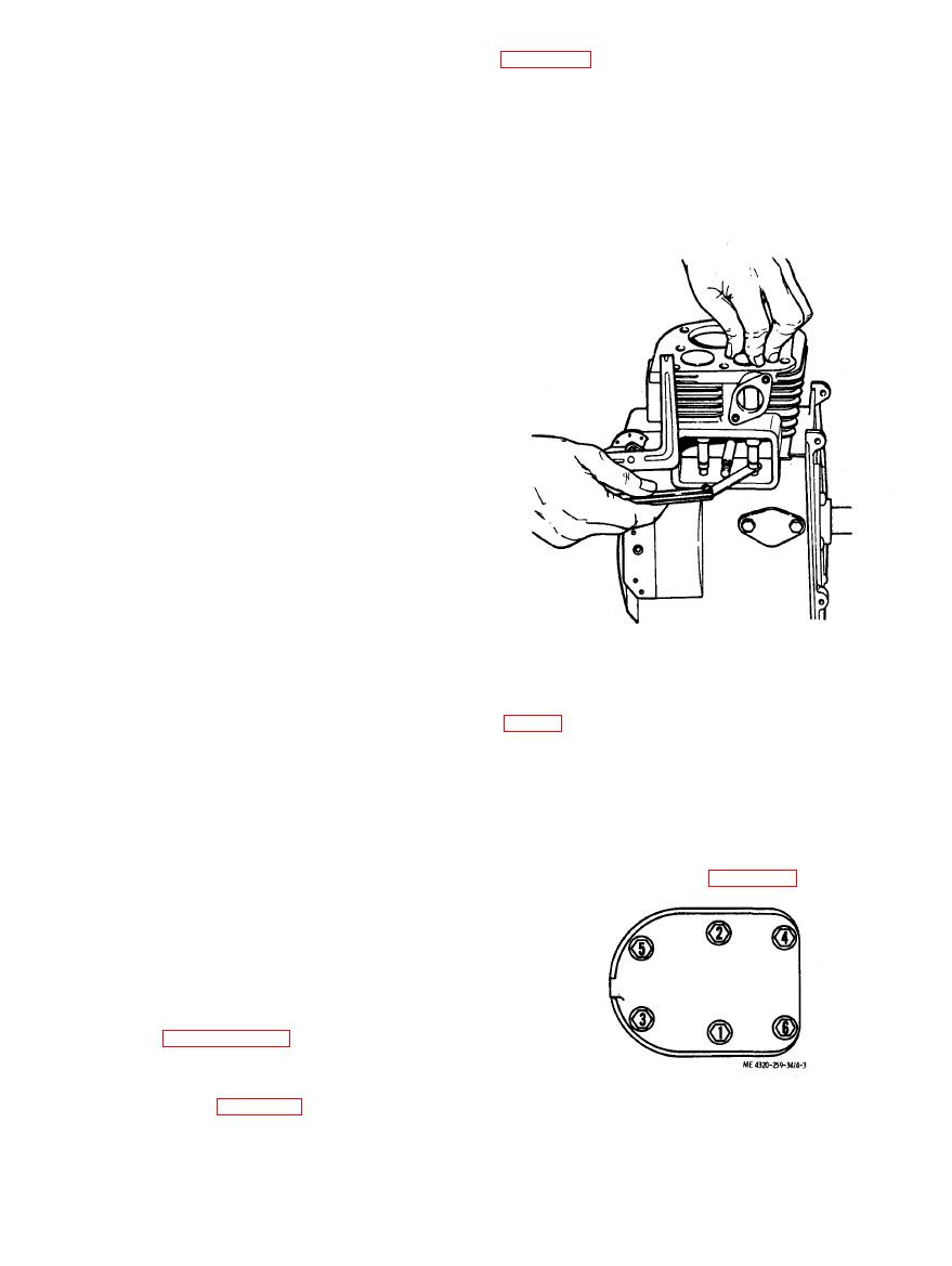
d. When installing the cylinder head (3), be sure
both intake and exhaust valves. Use a 15-degree
to use a new gasket (4). Tighten the cylinder head
cutter if necessary to narrow the valve seat.
bolts (1) to 16 to 17 foot-pounds. Tighten the bolts
h. Check the fit of the valves in the valve seats in
in the sequence shown in figure 4-3.
the block. A tight seal must be made. If necessary,
regrind the valves and valve seats. The valve head
angle is 45 degrees for both valves. The valve seat
angle is 89 degrees for both valves. Lap the valve to
the seat, using fine grade of grinding compound
and a hand valve grinder with a suction cup.
i. If the valve seat in the cylinder block cannot
be properly reground, replace the valve seat as
directed in paragraph 4-21 d.
Reassemble and install the valves and cylinder
head as shown in figure 4-1. Note the following:
a. Make sure the valve seats, ports, and valves
are thoroughly cleaned after regrinding or lapping.
|
|
Privacy Statement - Press Release - Copyright Information. - Contact Us |
