 |
|||
|
|
|||
|
Page Title:
Section II. CYLINDER HEAD AND VALVES |
|
||
| ||||||||||
|
|
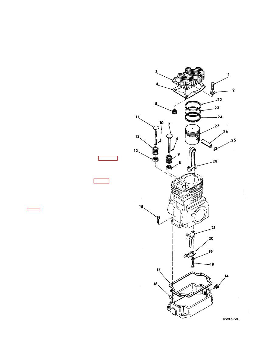 Table 4-1. Engine Fits, Tolerances, and Wear Limits--Continued
Dimension (in.)
Item
0.0007/0.0022
Ball bearing to seal plate (interference)
0.0004/0.0003
Ball bearing to crankshaft (interference to loose)
Section Il. CYLINDER HEAD AND VALVES
4-3. Description
a. The cylinder head is mounted on top of the
cylinder/block to seal the cylinder and to provide a
mounting for the spark plug. The cylinder head is
deeply finned to provide efficient dissipation of heat
caused by combustion in the cylinder.
b. The valves are mounted in the cylinder block
and are opened at the required time by cams on the
camshaft through valve tappets mounted in the
cylinder block. The valves are heavily spring loaded
to close when disengaged by the cams on the
cam shaft. The valves use positive valve rotators to
assure that the valves rotate a small amount each
time they are operated. This equalizes valve wear
and causes a wiping action which helps to assure a
good valve seat when the valves close.
b. Remove the spark plug, engine housing, and
the crankcase breather (TM 5-4320-259-12).
c. Make sure the engine is cooled to room
temperature. Remove the six bolts (1, fig. 4-1) and
flat washers (2) that secure the cylinder head (3) to
the cylinder block. Remove the cylinder head and
gasket (4).
KEY to fig. 4-1:
1. Cylinder head bolt
15.
Assembled washer screw
2. Flat washer
16.
Oil pan
3. Cylinder head
17.
Oil pan gasket
4. Cylinder head gasket
18.
Connecting rod cap screw
5. Spark plug insert
19.
Flat washer
6. Valve retaining pin
20.
Lock
21.
Connecting rod bearing cap
7. Intake valve
8. Valve rotator
22.
Compression ring
9. Valve spring
23.
Compression ring
10. Valve retaining pin
24.
Oil control ring
11. Exhaust valve
25.
Retainer ring
12. Valve rotator
26.
Piston pin
27. Piston
13. Valve spring
14. Oil pan drain plug
28. Connecting rod
|
|
Privacy Statement - Press Release - Copyright Information. - Contact Us |
