 |
|||
|
|
|||
|
|
|||
| ||||||||||
|
|
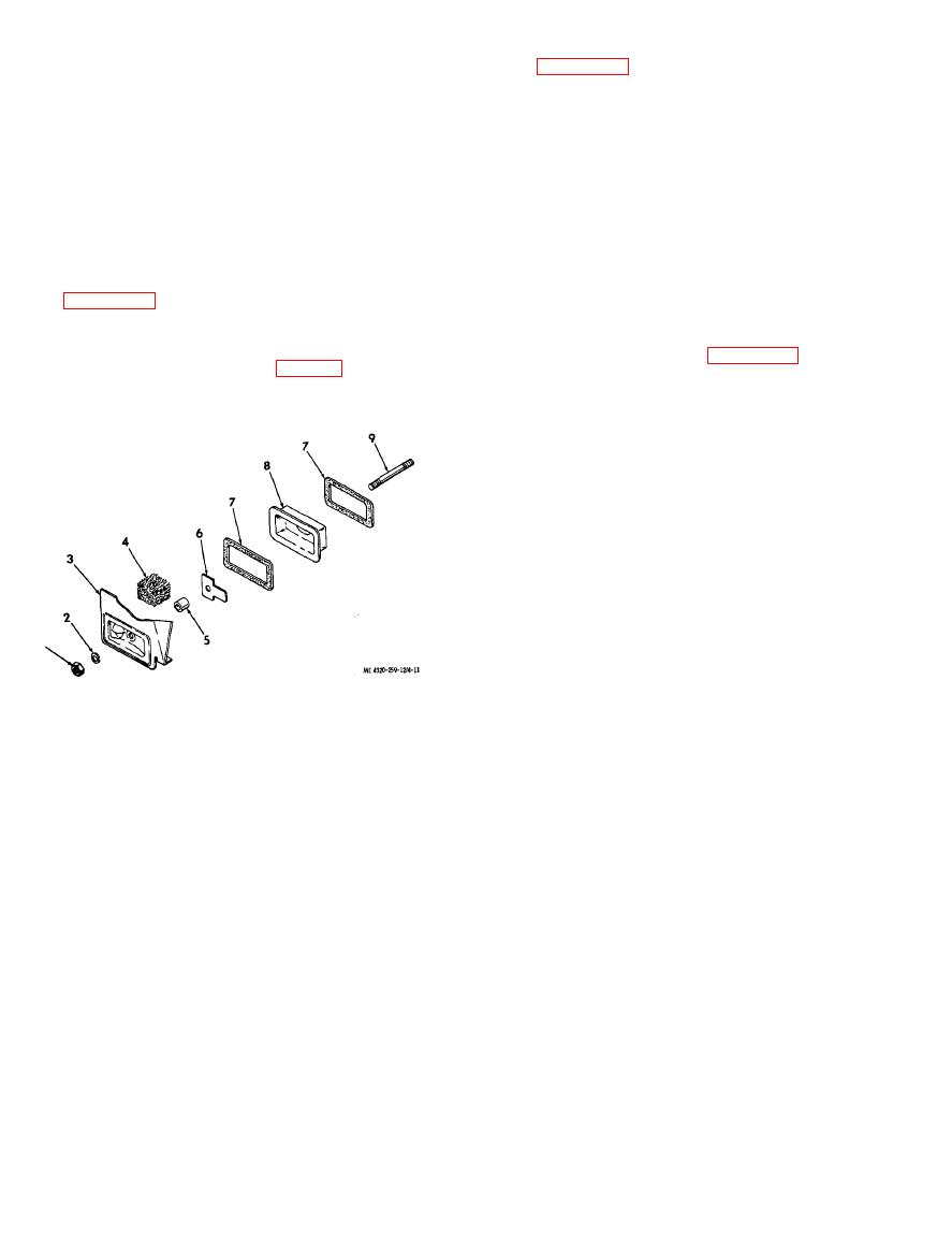 (2) Disassemble the breather assembly as
b. Cleaning and Inspection.
shown in figure 4-11.
(1) Clean all parts with an approved cleaning
b. Cleaning and Inspection.
solvent. Wirebrush the muffler to remove all rust
(1) Clean all parts with an approved cleaning
and corrosion.
solvent. Shake the filter free of solvent. Wipe all
(2) Inspect the muffler for cracks, holes, thin
other parts dry.
spots, and other damage that could affect its noise-
(2) Inspect the filter for matting, clogging,
reducing or spark-retarding characteristics.
and deterioration; replace a damaged filter.
Replace a damaged muffler.
(3) Inspect the reed and breather plate for
(3) Inspect all other parts for cracks, rusting,
cracks and distortion. The reed must make a good
signs of deterioration, and other damage; replace
seal against its seat on the breather plate. Replace
damaged parts.
dam aged parts.
c. Reassembly and Installation. Reassemble
( 4 ) Inspect all other parts for cracks,
and install the muffler and related parts as shown
distortion, and other damage; replace damaged
in figure 4-10.
parts.
a. Removal.
the engine crankcase as shown in figure 4-11. Make
(1) Remove the nut (1, fig. 4-11) and lock
sure all sealing surfaces are tight to prevent the
washer (2); remove the entire breather assembly
entry of dirt into the engine.
from the engine crankcase.
1.
Nut
2.
Lock washer
3.
Cover
4.
Filter
5.
Seal
6.
Breather reed
7.
Gasket
8.
Breather plate
9.
Stud
Section XI. MAINTENANCE OF PUMP ACCESSORIES
The hose ends are identical to those used on the
4-26. Description
suction hose.
a. One 10 foot, wire-reinforced, rigid-walled
c. Two 1 inch discharge nozzles are pro-
suction hose is provided with the pumping
vided with the pumping assembly. The nozzles
assembly. One end of the hose is fitted with a male
are the non-automatic type so that discharge stops
quick-disconnect coupling and the opposite end
immediately when the operating lever is released.
uses a female quick-disconnect coupling. One plug
The nozzles are provided with quick-disconnect
and one cap are provided to prevent the entry of
couplings, and dust plugs are provided to prevent
dirt into the hose.
the entry of dirt. A screen strainer in the spout
b. Two 50 foot, collapsible-walled discharge
prevents foreign particles from entering the fuel
hoses are provided with the pumping assembly.
|
|
Privacy Statement - Press Release - Copyright Information. - Contact Us |
