 |
|||
|
|
|||
|
Page Title:
Figure 4-5. Checking and adjusting breaker point opening. |
|
||
| ||||||||||
|
|
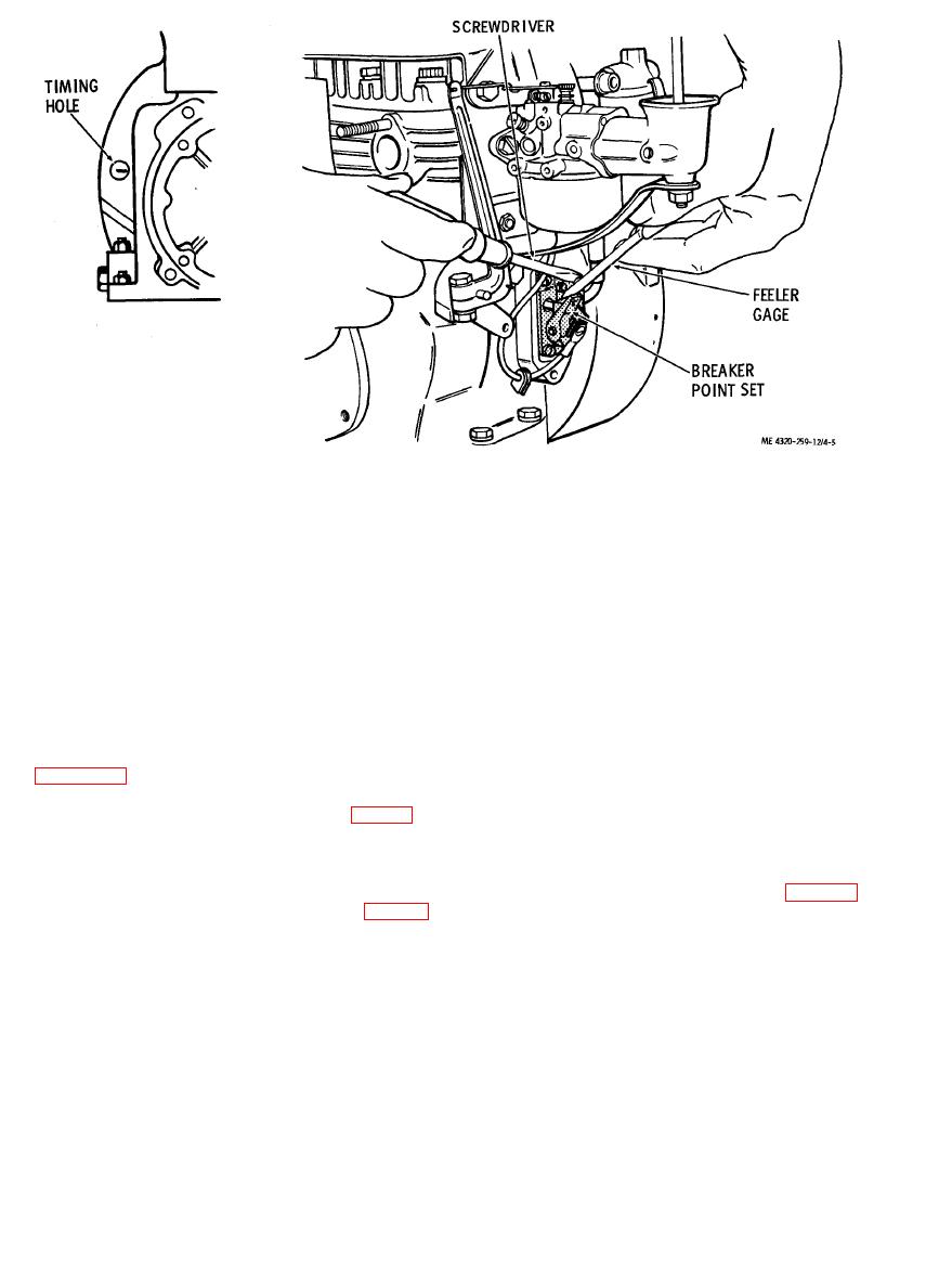 4. After all other parts are removed, the breaker rod
(3) Disconnect the spark plug cable from the
can be withdrawn from the bore in the engine
spark plug. Using the starting rope, turn over the
housing.
engine until the start of the compression stroke is
c. Cleaning and Inspection.
felt. Continue to rotate the flywheel until the "T"
mark appears in the center of the timing hole, while
(1) Clean all parts with an approved cleaning
solvent; dry thoroughly.
also watching the breaker points.
(4) With the "T" mark centered in the timing
(2) Inspect the breaker points for burning,
hole, the breaker points should just start to open.
pitting, and other damage. Use a point file to clean
up slightly pitted breaker points. Replace breaker
Continue to rotate the flywheel until the breaker
points are fully open.
point set if badly pitted or burned.
(5) Check the point opening by inserting a
(3) Inspect the breaker lead assembly for
feeler gage between the breaker points as shown in
broken terminals, damaged insulation, and other
damage; replace the breaker lead if damaged.
0.020 inch. If breaker point opening is not
(4) Inspect the breaker rod for bends, wear,
correct, loosen the machine screw (7, fig. 4-4)
and scoring; replace a damaged breaker rod.
slightly and use a screwdriver to adjust the breaker
(5) Replace any other parts that are bent,
cracked, or defective.
point gap to the required opening. Tighten the
machine screw.
d. Reassembly and Installation. Reassemble
b. Removal and Disassembly. Remove and
and install the breaker points as shown in figure 4-
4. After installation, adjust as directed in sub-
disassemble the breaker points as shown in figure 4-
paragraph a above.
|
|
Privacy Statement - Press Release - Copyright Information. - Contact Us |
