 |
|||
|
|
|||
|
Page Title:
Section VIII. MAINTENANCE OF IGNITION SYSTEM |
|
||
| ||||||||||
|
|
 Section VIII. MAINTENANCE OF IGNITION SYSTEM
4-14. Description
a. The ignition system consists of a magneto, its
breaker points, and the spark plug which uses a
shielded spark plug cable. The ignition system
supplies a spark at the proper instant necessary to
ignite the fuel-air mixture in the cylinder at the
height of the compression stroke.
b. The magneto consists of an electrical coil
mounted on a laminated steel frame, positioned
within the flywheel. Permanent magnets are case
into the flywheel. As the magnets rotate past the
coil, they induce an electrical current in the elec-
trical coil. The electrical coil has a primary winding
and a secondary winding. The electrical current in
the primary winding induces a high-voltage current
in the secondary winding. The voltage peak is
reached as the breaker points are opened to break
the primary circuit, causing a rapid decay of the
magnetic field. A capacitor in the circuit speeds the
collapse of the magnetic field to cause a hotter
spark at the spark plug. The capacitor also
minimizes burning of the contact points.
c. The breaker point set is opened by a cam on
the camshaft through a breaker rod which rides
against a lobe on the camshaft. The timing of the
point opening is critical and is done with the aid of
timing marks on the engine flywheel. The timing
setting can be done either by static adjustment or
by use of a timing light.
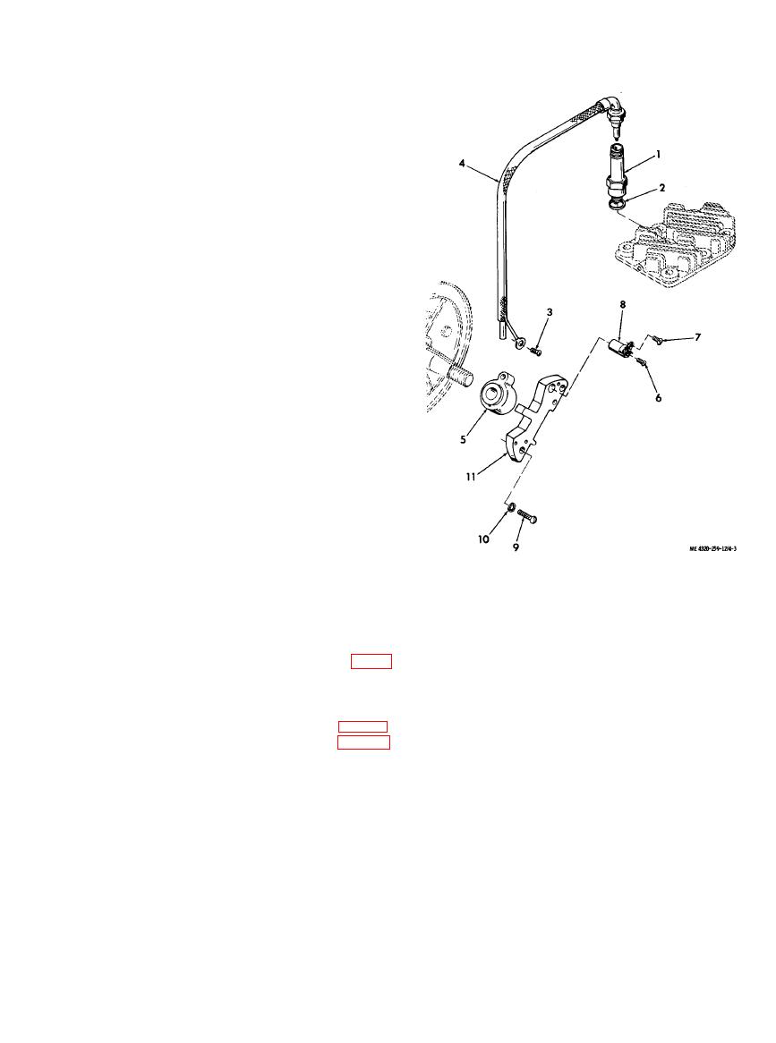
d. The spark plug is a radio-shielded type,
designed to minimize emission of radio interference
1.
Spark plug
resulting from the arcing of the plug. The spark
2.
Gasket
plug cable is also shielded to prevent emission of
3.
Machine screw
radio frequency interference.
4.
Spark plug cable
5.
Magneto coil
4-15. Spark Plug and Cable
6.
Machine screw
a. Removal.
7.
Machine screw
(1) Disconnect the spark plug cable (4, fig. 4-
8.
Capacitor
3) from the spark plug (1); remove the spark plug
9.
Machine screw
10.
Lock washer
and gasket (2) from the cylinder head.
11.
Magneto frame
(2) To remove the spark plug cable (4), it is
necessary to remove the blower housing (para 4-
12), and the starter pulley and flywheel (para 4-
13). Disconnect the cable shielding and pull the
end of the cable from the cable socket in the
magneto coil (5).
|
|
Privacy Statement - Press Release - Copyright Information. - Contact Us |
