 |
|||
|
|
|||
|
|
|||
| ||||||||||
|
|
 TM 5-4320-258-34
to the crankshaft, using the starting jaw (1) and collar
(2).
(3) Install the governor on the engine (TM
5-4320-258-12). Time the magneto (TM 5-4320-258-
12).
4-9.
Flywheel and Flywheel Housing
a. Removal.
Remove the flywheel and
flywheel housing as follows:
(1) Remove the six nuts (5, fig. 4-14) and
lock washers (6) that secure the flywheel (7) and ring
gear (8) to the crankshaft (40); remove the flywheel.
(2) Remove the cap screws (11, fig. 4-22),
shoulder screws (13), and lock washers (12 and 14) that
secure the flywheel housing (15) to the block (35);
remove the flywheel housing and gasket.
b. Cleaning, Inspection, and Repair.
(1) Clean the flywheel and flywheel
housing with cleaning solvent (FED. Spec. P-D-680);
dry thoroughly.
(2) Inspect the flywheel housing for cracks,
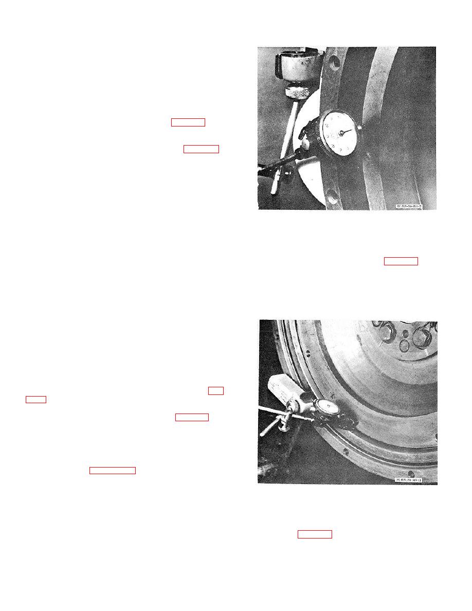
Figure 4-10. Checking flywheel runout.
distortion, and damaged threads; replace a damaged
flywheel housing.
(4) Check flywheel eccentricity by
(3) Inspect the flywheel for chipped,
mounting a dial indicator so that it indicates the inside
cracked, or broken teeth on the ring gear, distortion,
diameter of the flywheel counterbore (fig. 4-11); rotate
worn or out-of-round bolt holes, and other damage. If
the crankshaft through one revolution. If the flywheel is
the ring gear is damaged, replace as follows:
eccentric more than 0.008 inch, loosen and retighten the
Caution: When cutting the ring gear, be
flywheel mounting bolts and recheck eccentricity. If
extremely careful not to damage the flywheel.
eccentricity still exceeds 0.008 inch, replace the
(a) Cut the ring gear with a torch or
flywheel.
hack saw and remove the ring gear from the flywheel.
(b) Heat the replacement ring gear in
an oven and cool the flywheel in water or in a
refrigerator.
(c) Position the replacement ring gear
on the flywheel. As the ring gear and flywheel approach
the same temperature, the ring gear will contract to a
tight fit on the flywheel.
c. Installation.
(1) Position the flywheel housing (15, fig.
(13), cap screws (11), and lock washers (12 and 14).
(2) Position the flywheel (7, fig. 4-14) on
the crankshaft (40); secure with six bolts (9), lock
washers (6), and nuts (5). Tighten the nuts to 35 to 40
foot-pounds torque.
(3) Check flywheel runout by mounting a
dial indicator so that it indicates the flat vertical surface
of the flywheel (figure 4-10); rotate the crankshaft
through one full revolution. Hold pressure against the
flywheel to eliminate crankshaft end play. If flywheel
Figure 4-11. Checking flywheel eccentricity.
runout exceeds 0.008 inch, remove the flywheel and
clean the crankshaft flange and flywheel seat. Install
the flywheel and recheck runout. If runout still exceeds
(5) Check runout of the flywheel housing
0.008 inch, replace the flywheel.
face by mounting a dial indicator so that it indicates the
housing face (fig. 4-12); rotate the crankshaft through
one revolution. Hold pressure against the flywheel to
eliminate end play. If runout exceeds
4-17
|
|
Privacy Statement - Press Release - Copyright Information. - Contact Us |
