 |
|||
|
|
|||
|
|
|||
| ||||||||||
|
|
 TM 5-4320-258-34
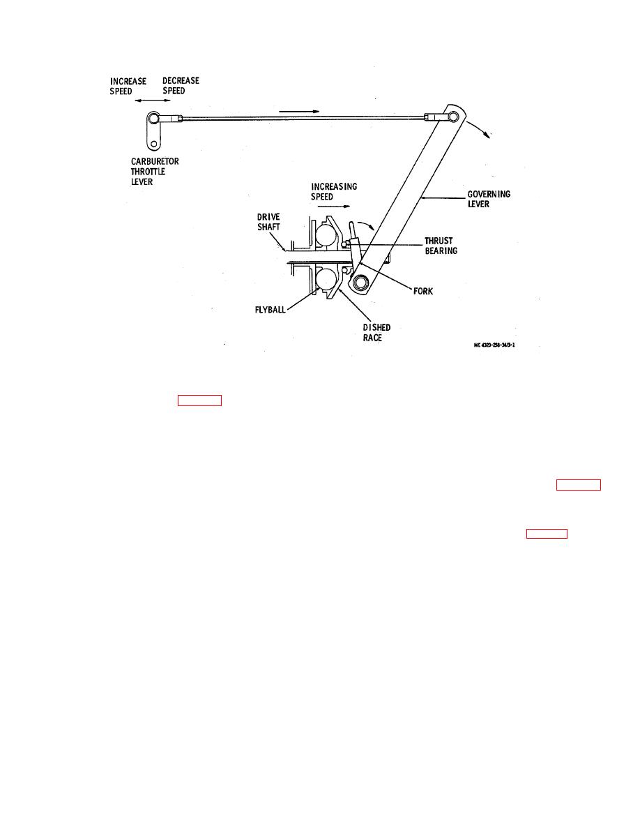
Figure 3-1. Operation of engine speed regulating system.
d. The engine is protected from overspeeds
governor must be 'pressed to reset the switch if the unit
it tripped by an overspeed condition.
by the overspeed governor (fig. 3-6). The overspeed
3-2.
Fuel Tank
governor is mounted on an adapter on the top center of
a. Removal and Disassembly.
the cylinder head. It is driven by a shaft which engages
the top of the oil pump drive shaft which is, in turn,
(1) Disconnect the fuel lines and fittings
driven by a geared portion of the camshaft. The
from the fuel tank (TM 5-4320-258-12)
overspeed governor is adjusted to stop the engine if
(2) Remove the battery box from the skid
crankshaft speed exceeds 2700 rpm. The stopping is
base.
accomplished by grounding the magneto primary
(3) Remove the drain plug (1, fig. 3-2)
through a switch which closes in the governor
from the bottom of the fuel tank and catch the fuel in a
mechanism. A reset button at the top of the overspeed
suitable container.
KEY to fig. 3-2:
1. Drain plug
2. Cap screw
3. Lock washer
4. Fuel tank cap
5. Chain
6. Screen
7. Nut
8. Lock washer
9. Fill plate
10. Gasket
11. Suction pipe
12. Pipe plug
13. Nut 1
14. Autofill float valve
15. Fuel level gage
16. Fuel tank
3-2
|
|
Privacy Statement - Press Release - Copyright Information. - Contact Us |
