 |
|||
|
|
|||
|
Page Title:
Section XIV. MAINTENANCE OF PUMP AND |
|
||
| ||||||||||
|
|
 Section XIV. MAINTENANCE OF PUMP AND
COUPLING
4-46. Description
a. The pump is secured to the flywheel housing of
the engine and to the skid which mounts both the engine
and pump. The pump shaft is secured to the engine
flywheel through a flexible coupling, one member of
which is keyed to the pump shaft and the other half of
which is bolted to a drive plate that is bolted to the
flywheel.
b. Pump alignment is attained by the installation of
horseshoe-type shims which are placed between the
mounting feet of the pump body and the skid. Adding or
removing shims raises or lowers the pump as required
to aline it with the engine flywheel and flywheel housing.
The engine and pump must be closely alined to assure a
smooth transfer of power from the engine to the pump,
even though the flexible coupling will tolerate a small
amount of misalignment of the drive system.
4-47. Centrifugal Pump
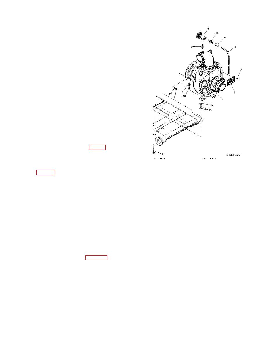
a. Removal.
(1) Remove the drain plug (fig. 1-1) from the
centrifugal pump.
(2) Disconnect all suction and discharge
piping from the pump.
(3) Remove the air eliminator valve (items 1
1.
Tube
9.
Nut
through 5, fig. 4-39).
2.
Tube nut
10.
Lock washer
(4) Support the weight of the pump with a
3.
Connector
11.
Nut
hoist or crane hooked into the lifting eye welded onto the
4.
Air eliminator valve
12.
Lock washer
discharge elbow.
6.
Pipe nipple
13.
Centrifugal pump
(5) Remove the nuts (11) and lock washers
6.
Screw
14.
Shim
(12) that secure the bearing housing of the pump (13) to
7.
Identification plate
15.
Shim
the flywheel housing of the engine.
8.
Cap screw
16.
Stud
(6) Remove the cap screws (8), nuts (9), and
lock washers (10) that secure the pump to the skid.
Figure 4-39.
Centrifugal pump, removal and
Operate the hoist or crane so that the pump feet just
installation.
clear the skid. Pull straight out on the pump to
disengage the pump half of the flexible coupling from
(3) Inspect the pump for a cracked or dented
the engine half of the coupling. Take care to prevent
housing, suction flange, or discharge elbow. Attempt to
losing the cushions that are installed between the
turn the pump shaft. It must turn freely and smoothly,
coupling halves. Remove the pump and shims (14 and
without catching or binding. Reach into the pump
15).
through the suction flange and check the operation of
the check valve. It must operate freely and must make
(7) Remove the coupling (para 4-48a).
a good seal against its seat.
Report any pump
deficiencies to direct support maintenance.
b. Cleaning and Inspection.
(4) Inspect the air eliminator valve for rough
or catching operation and for cracked or damaged
(1) Clean the exterior of the pump with a
threads. Replace a damaged valve.
cloth dampened with cleaning solvent (fed. spec.P-D-
(5) Inspect all other parts for cracks,
680); dry thoroughly.
distortion, and other damage; replace damaged parts.
(2) Wash the air eliminator valve and related
parts with cleaning solvent (fed. spec. PD-680) ; dry
thoroughly.
4-43
|
|
Privacy Statement - Press Release - Copyright Information. - Contact Us |
