 |
|||
|
|
|||
|
Page Title:
Suction and Discharge Gages, Lines, and Fittings |
|
||
| ||||||||||
|
|
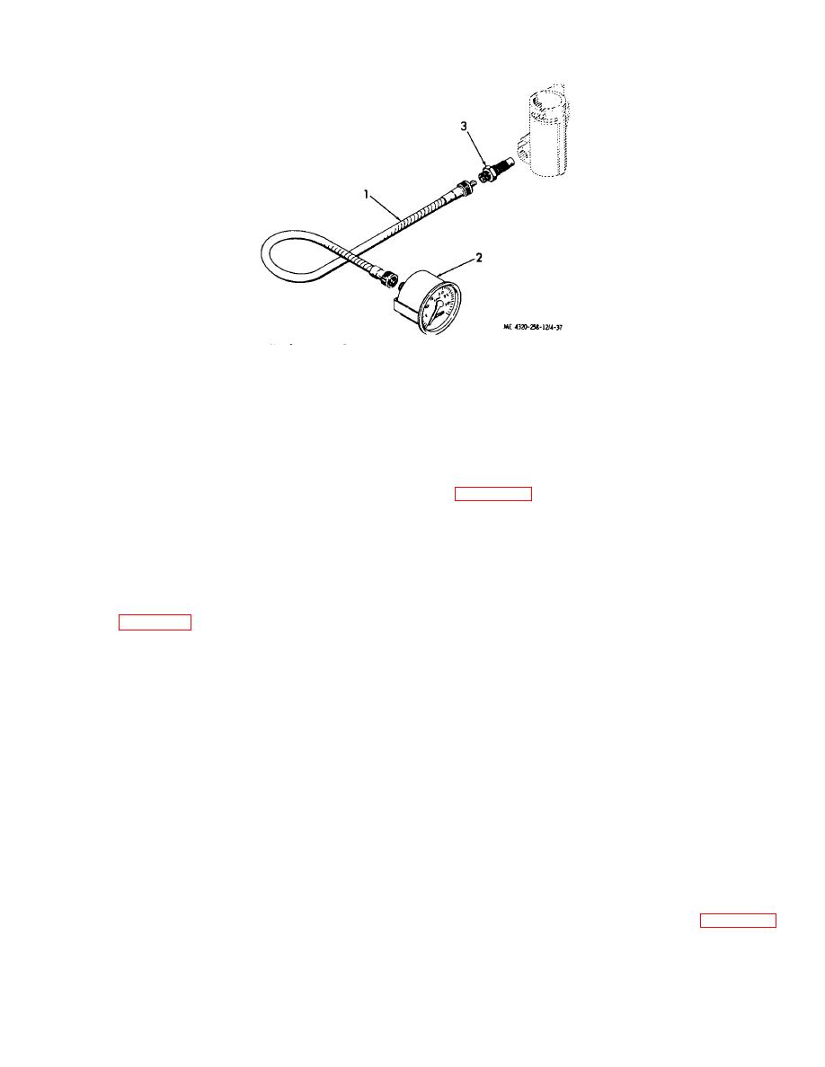 1. Tachometer shaft
3.
Tachometer drive
2. Tachometer-hourmeter
Figure 4-37. Tachometer and drive, exploded view.
coupling nuts. Replace a damaged tachometer shaft.
c. Installation. Installation is the reverse of removal; refer to figure 4-37. After installation, start the engine and
check the tachometer for proper operation.
4-45. Suction and Discharge Gages, Lines, and Fittings
a. Removal and Disassembly.
(1) Remove and disassemble the lines and fittings from the suction and discharge gages and from the pump
as shown in figure 4-38.
(2) Remove the cap screws (20 and 24, fig.4-38), nuts (21 and 25), and lock washers (22 and 26) that secure
the suction and discharge gages (23 and 27) to the control panel; remove the gages.
b. Cleaning and Inspection.
(1) Clean the suction and discharge gages with a cloth dampened with cleaning solvent (fed. spec. P-D-680);
dry thoroughly.
(2) Clean all lines and fittings by washing in cleaning solvent (fed. spec. P-D-680). Shake off excessive
solvent.
(3) Inspect the suction and pressure gages for cracked dial glass, binding or sticking needle movement,
illegible dial faces, evidence of water entry, and other damage. If possible, check the operation against master gages to
assure the accuracy of the indication. Replace damaged gages.
(4) Inspect the hoses for cuts, abrasions, leaks, damaged threads, and other damage; replace damaged
hoses.
(5) Inspect .the valves for cracks, damaged threads, and for catching or binding of the valve stem. Replace
damaged valves.
(6) Inspect all other parts for cracks, distortion, damaged threads, and other damage; replace damaged parts.
c. Reassembly and Installation. Install the suction and discharge gages, lines, and fittings as shown in figure 4-38.
After assembly, start the pump and check for leaks. Correct any leaks noted.
4-41
|
|
Privacy Statement - Press Release - Copyright Information. - Contact Us |
