 |
|||
|
|
|||
|
Page Title:
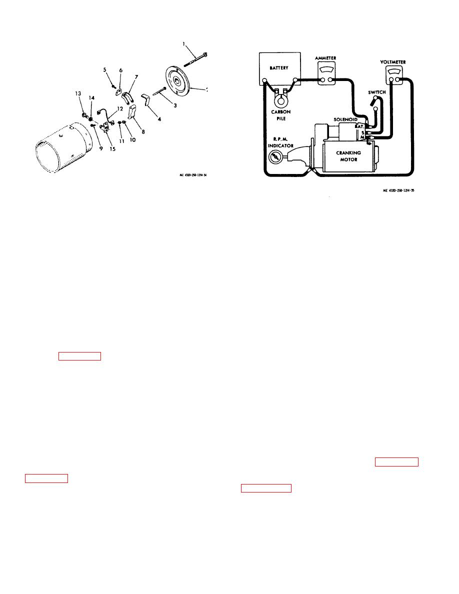
Figure 4-34. Engine starter brushes, exploded view. |
|
||
| ||||||||||
|
|
 1. Thru bolt
8.
Insulated brush
2. Commutator end
holder
frame
9.
Brush lead screw
Figure 4-35. Engine starter test setup.
3. Support pin
10.
Nut
4. Brush spring
11.
Lock washer
open and the carbon pile rheostat at a non-load
5. Brush screw
12.
Grounded brush lead
condition. Just prior to closing the switch, operate the
6. Brush
13.
Brush support screw
carbon pile rheostat to load the battery.
7. Grounded brush
14.
Washer
holder
15.
Brush support
(3) Close the switch and adjust the carbon
pile rheostat to provide a 20-volt indication on the
Figure 4-34. Engine starter brushes, exploded view.
voltmeter. The starter must operate at a high rate of
speed. Allow the starter to gain full speed rotation and
(3) Remove the screws (13) and washers (14)
check the indication of the tachometer. It must read
that secure the brush leads (12) to the brush support
3300 and 5600 rpm.
(15); remove the brush leads.
(4) With the starter operating in the required
(4) Replace brushes if they are chipped, oil
speed range, check the indication on the ammeter.
soaked, or worn to less than 5/16 inch. Replace any
Current draw shall not exceed 40 to 75 amperes. This
other parts that are cracked, worn, or distorted.
includes the draw of the solenoid.
(5) Install the brushes and related parts as
(5) Open the switch and disconnect the
shown in figure 4-34. Before. installing the commutator
starter. Disconnect the carbon pile rheostat to prevent it
end frame (2), seat the brushes on the commutator,
from draining the battery.
using 00 sandpaper.
(6) If the starter fails to operate within the
required range of speeds and amperages at 20 volts,
Note. The commutator on the armature shaft
replace the starter.
must be smooth and concentric, free from burrs,
scoring, high segments, or other damage. Replace the
e. Installation.
engine starter if the commutator is damaged (6) Install
the commutator end frame (2) with the thru bolts (1).
(1) Position the engine starter (7, fig. 426)
with its assembled solenoid switch (6) on the flywheel
d. Starter Bench Testing. Check the operation of
housing of the engine; secure with three cap screws and
the starter on a bench as follows:
lock washers.
(2) If necessary, refer to figure 1-3 for
(1) Set up the starter for testing as shown in
connection information.
(3) Attempt to start the engine as directed in
prior to the test.
and
easily.
Caution: Take care not to exceed a 20-volt
input to the starter during this test. Higher voltages
may cause the starter to throw its windings.
(2) Make all test setups with the switch
4-38
|
|
Privacy Statement - Press Release - Copyright Information. - Contact Us |
