 |
|||
|
|
|||
|
|
|||
| ||||||||||
|
|
 (1) Installation is the reverse of removal.
Refer to items 1 through 15 in figure 4-31.
(2) Connect the electrical leads to the
alternator. If necessary, refer to the wiring diagram in
(3) Engage the fan belt on the alternator
pulley and tighten the belt (para 4-30a).\par
4-38. Voltage Regulator
Caution: Disconnect the battery cable (6,
fig.4-1) from the positive battery terminal (4) before
disconnecting any other leads from the engine
components. This will prevent shorts which could
damage the alternator, voltage regulator, and other
parts.
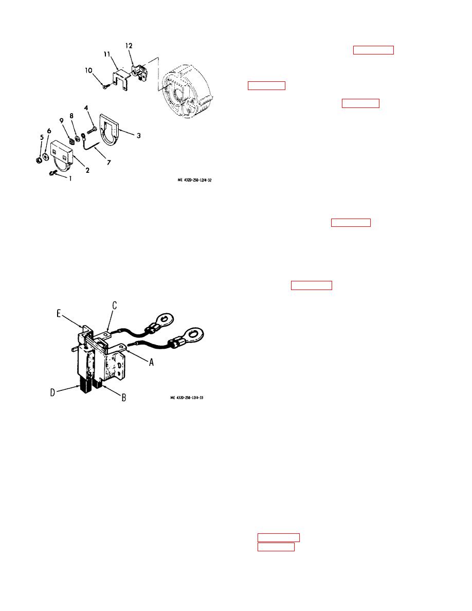
1. Assembled washer
7.
Electrical lead
a. Adjustment.
If adjustment of the voltage
screw
8.
Flat washer
regulator is indicated when making the voltage regulator
2. Brush cover
9.
Bushing
operating voltage test (para 4-36d), adjust the voltage
3. Gasket
10.
Machine screw
regulator as follows:
4. Terminal screw
11.
Insulator
5. Nut
12.
Brush assembly
(1) Remove the seal screw from the voltage
6. Insulating washer
regulator cover to provide access to the adjusting screw
of the variable resistor in the voltage regulator.
Figure 4-32. Alternator brush assembly, exploded
(2) With the battery charging system set up
view.
as shown in figure 4-29, adjust the setting of the variable
resistor with a No. 0 Phillips screwdriver to provide a
voltage of 28.4 + 0.4 volts when the battery is at full
charge and the alternator output current is 8 to 10
amperes.
(3) After adjustment, install the seal screw in
the voltage regulator cover.
b. Removal.
(1) Disconnect the electrical leads from the
voltage regulator. Tag leads to facilitate reassembly.
(2) Remove the three cap screws (16, fig.
431), nuts (17), and lock washers (18) that secure the
voltage regulator to the mounting bracket; remove the
Figure 4-33.
Alternator brush assembly,
voltage regulator.
showing continuity paths.
c. Cleaning and Inspection.
entering the interior of the alternator.
Wipe the
alternator dry.
(1) Clean the voltage regulator with a cloth
dampened with cleaning solvent (fed. spec. P-D680);
(2) Inspect the alternator for cracks, signs of
dry thoroughly.
overheating, damaged terminals, and damaged internal
(2) Inspect the voltage regulator for cracks,
wiring.
signs of overheating, loose or damaged terminals, and
(3) Check the alternator rotor shaft for free
other damage; replace a damaged voltage regulator.
rotation. The shaft must turn freely and smoothly
without catching or binding. Replace the alternator if it
d. Installation. Installation of the voltage regulator
is damaged.
is the reverse of removal. Refer to items 16 through 19
of figure 4-31. If necessary, refer to the wiring diagram
d. Installation.
in figure 1-3 for connection requirements.
4-36
|
|
Privacy Statement - Press Release - Copyright Information. - Contact Us |
