 |
|||
|
|
|||
|
Page Title:
Figure 4-31. Battery charging system, exploded view. |
|
||
| ||||||||||
|
|
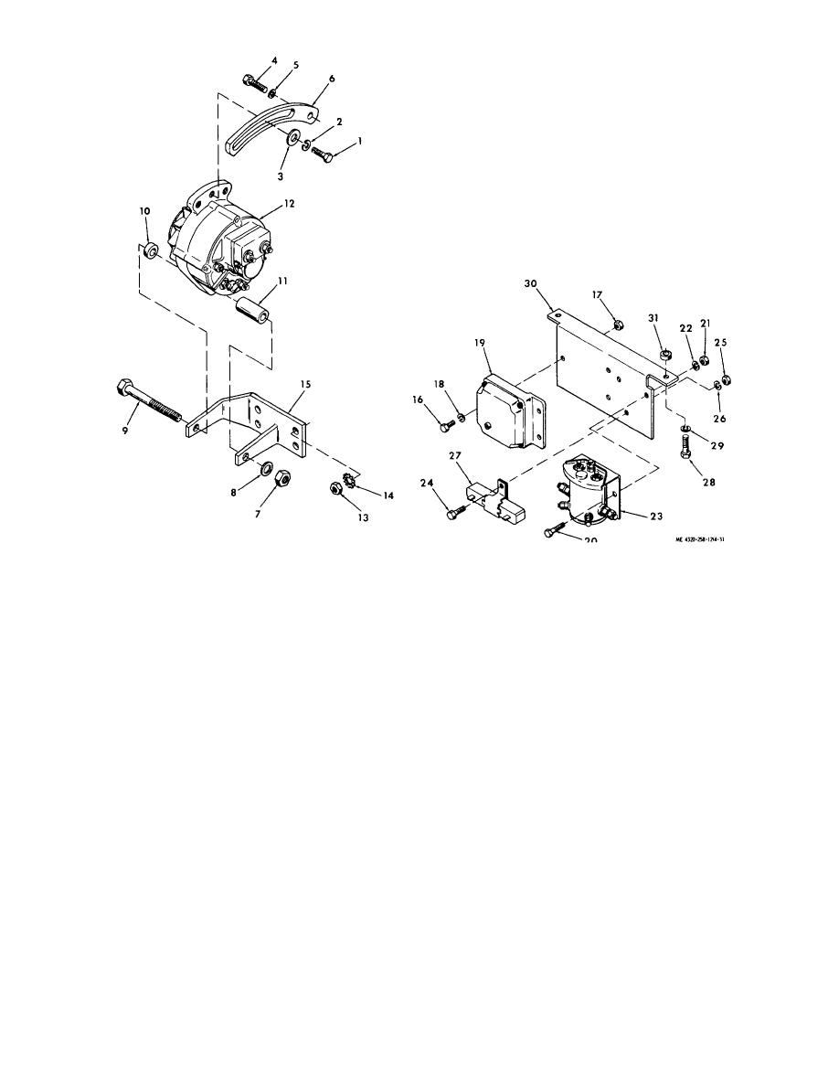 1.
Adjusting screw
12.
Alternator
22.
Lock washer
2.
Lock washer
13.
Nut
23.
Reverse polarity protector
3.
Flatwasher
14.
Lock washer
24.
Cap screw
4.
Strap mounting screw
15.
Alternator mounting bracket
26.
Nut
5.
Lock washer
16.
Cap screw
26.
Lock washer
6.
Adjusting strap
17.
Nut
27.
Excitation resistor
7.
Nut
18.
Lock washer
28.
Cap screw
8.
Flat washer
19.
Voltage regulator
29.
Lock washer
9.
Bolt
20.
Cap screw
30.
Mounting bracket
10.
Spacer
21.
Nut
31.
Spacer
11.
Spacer
Figure 4-31. Battery charging system, exploded view.
between point E and points A or C.
(6) Use a new brush assembly if the inspection indicates faults.
(7) Position the brush assembly (12, fig 4-32) and insulator (11) on the alternator; se cure with two machine
screws (10).
(8) Connect the electrical leads (7) from the brush assembly to the brush cover (2) with the terminal screws
(4), nuts (5), insulating washers (6), and washers (8). Make sure the bushings (9) are in place.
(9) Position the brush cover (2) on the alternator; secure with two assembled washer screws (1).
c. Cleaning and Inspection.
(1) Clean the exterior of the alternator with a cloth dampened with cleaning solvent (fed. spec.P-D-680).
Take care to prevent the solvent from
4-35
|
|
Privacy Statement - Press Release - Copyright Information. - Contact Us |
