 |
|||
|
|
|||
|
Page Title:
Figure 4-29. Voltage regulator operating voltage test setup. |
|
||
| ||||||||||
|
|
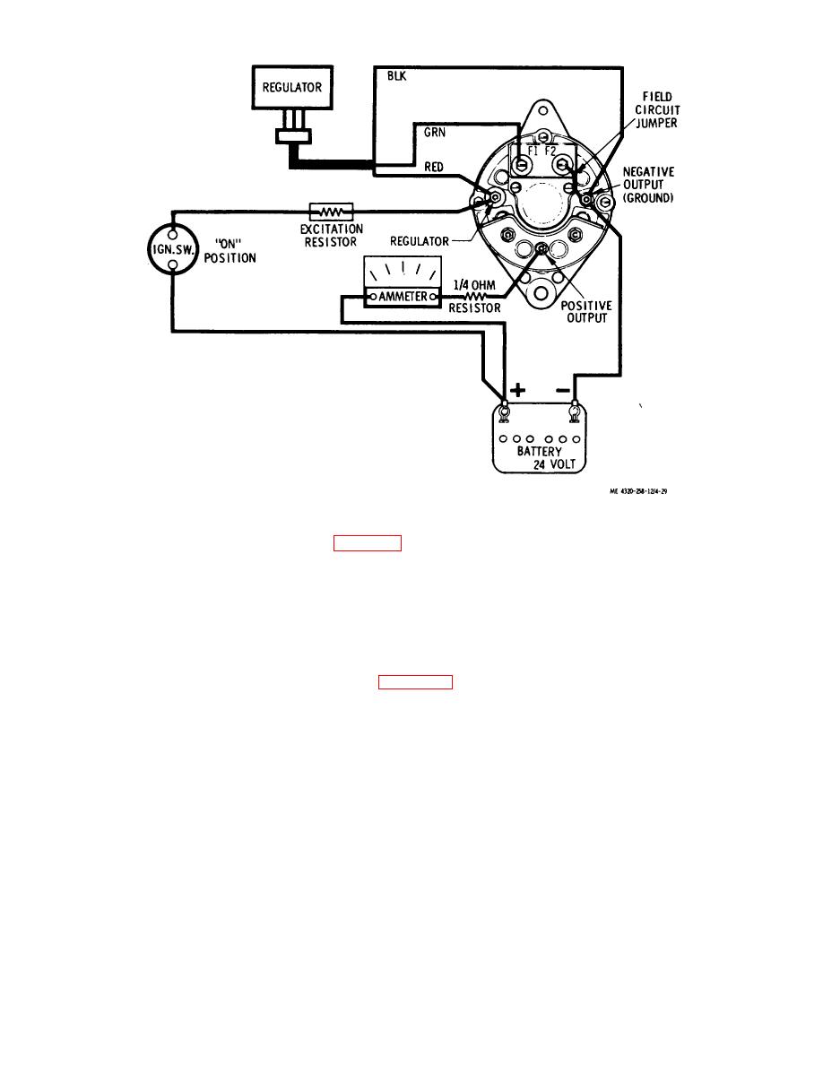 Figure 4-29. Voltage regulator operating voltage test setup.
(c) Low voltage regulator setting (para 4-38a).
(d) Defective regulator.
(5) Correct the cause of the overvoltage or undervoltage condition and recheck the voltage regulator operating voltage.
When tests are completed, disconnect the 1/4-ohm resistor from the circuit.
e. Alternator Output and System Test.
(1) Conduct this test with the battery disconnect switch in ON position, the ignition switch in ON position, the
engine running, and the equipment set up as shown in figure 4-30. At the start, set the carbon pile resistor to minimum
current drain. The ammeter must be adjusted to read in the 0 to 100 ampere scale.
(2) With the engine running at fast idle, adjust the carbon pile to provide a 20-ampere charge rate. Maintain
this for a few minutes to warm up the components.
(3) Use a tachometer to check the alternator speed. Adjust engine speed to maintain an alternator speed of
3000 to 5000 rpm.
(4) Adjust the carbon pile rheostat to attain a maximum current reading on the ammeter.
Maximum current output must be 30 amperes minimum, at 25 to 28 volts.
Caution: Unload the carbon pile rheostat immediately after completion of the test to prevent discharge of
the battery.
(5) Readjust the carbon pile rheostat for a 10-ampere output of the alternator. Check the voltage drop
between the alternator and battery at this output. If the voltage drop exceeds 0.3 volt, check battery cable connections
for high resistance connections.
4-37. Alternator
Caution: Disconnect the battery cable (6, fig.4-1) from the positive battery terminal (4) before disconnecting any
other leads from the engine components. This will prevent shorts which
4-33
|
|
Privacy Statement - Press Release - Copyright Information. - Contact Us |
