 |
|||
|
|
|||
|
Page Title:
Figure 4-27. Electrical system setup for battery voltage and isolation diode test. |
|
||
| ||||||||||
|
|
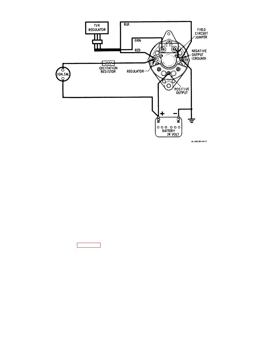 Figure 4-27. Electrical system setup for battery voltage and isolation diode test.
mines if the isolation diode is conducting alternator energy. If the isolation diode is open, battery charge cannot be
provided and may result in damage to the rectifier diodes and to the voltage regulator.
(1) Refer to figure 427 for the electrical circuit setup for this test. With the battery disconnect switch and the
ignition switch both in the ON positions and the engine running at fast idle, check the voltage across the negative output
terminal and the regulator terminal of the alternator, then check the voltage from the negative output terminal to the
positive output terminal of the alternator.
(2) The positive output of the alternator must be 28.6 +0.4 volts. The negative to regulator terminal output
must be between 0.8 and 1.2 volts higher than the positive output voltage.
(3) If only battery voltage is indicated at the positive output terminal, the isolation diode is open and the
alternator should be replaced.
c. Field Current Test. This test is designed to measure the alternator field current draw in amperes. The brushes and
sliprings are part of the field circuit in this test. Excessive field current may produce high alternator output and may result
in damage to the voltage regulator. Low field current will result in low alternator output.
(1) With the engine stopped, the ignition switch at OFF, and the battery disconnect switch positioned to ON,
set up the field test as shown in figure 4-28. Note that the regulator field lead is disconnected from the Fl terminal of the
alternator.
(2) With the field rheostat set to the maximum resistance position, set the ammeter to read in the 0 to 10
ampere range.
(3) Reduce rheostat resistance carefully, watching the ammeter. If the ammeter indicates more than 3.5
amperes, the field circuit is faulty. Stop the test immediately. Remove the rear cover and check the brushes and
sliprings for faults. Correct any shorted or grounded conditions of the sliprings or brushes.
(4) The normal field current is 2.0 to 3.0 amperes when field rheostat resistance is reduced to zero.
(5) With the ammeter registering the field
4-31
|
|
Privacy Statement - Press Release - Copyright Information. - Contact Us |
