 |
|||
|
|
|||
|
Page Title:
Figure 4-13. Magneto and governor installation. |
|
||
| ||||||||||
|
|
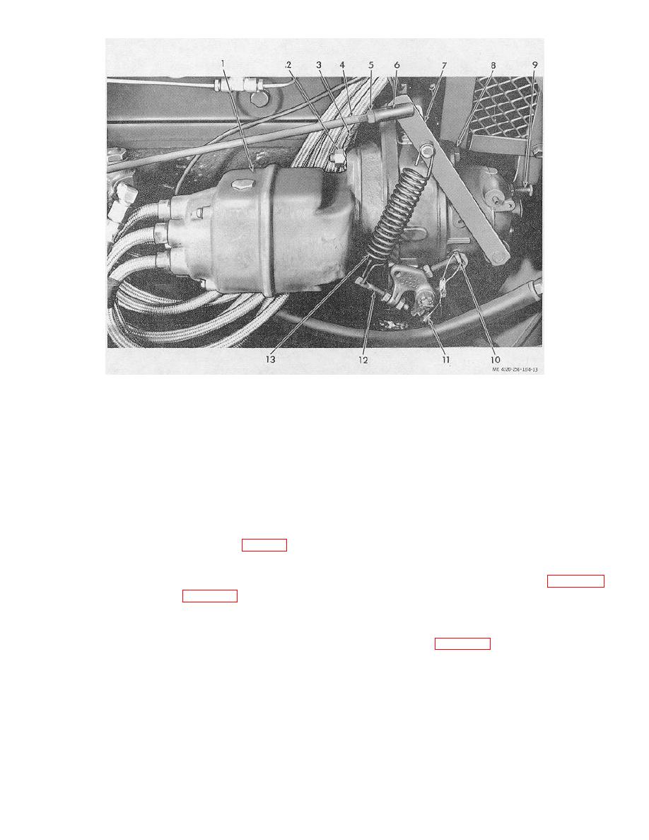 1.
Magneto
5. Nut
10. Speed adjusting lock screw
2.
Nut
6. Throttle rod ball joint
11. Speed adjusting screw
3.
Magneto ground strap
7. Throttle operating lever
12. Sensitivity adjusting screw
4.
Governor-to-carburetor
8. Mounting screw
13. Governor spring
control rod
9. Surge adjusting screw
Figure 4-13. Magneto and governor installation.
locking nut. If the carburetor and linkage are properly
(3) Inspect the governor for cracks, and
adjusted, surge will disappear.
missing parts, wear, and other obvious damage. Check
the rotation of the governor drive shaft. It must turn
(6) When the governor adjustment is
freely without catching or binding. Check the movement
completed, tighten the speed adjusting lock screw (10)
of the governing shaft in its needle bearings. It must
to lock the cam in position. Make sure all locking nuts
pivot freely without catching or binding and without
are tightened.
excessive play. Refer a damaged governor to direct
b. Removal.
support maintenance.
(1) Disconnect the ball joint (16, fig. 4-11) on
d. Installation.
governor-to-carburetor control rod (18) from the lever on
(1) Install the governor by reversing the removal
the governor.
procedure. Refer to items 27 through 37 in figure 4-11.
(2) Remove the governor and related parts as
(2) Adjust the governor as directed in sub-paragraph a
shown in items 27 through 37, figure 4-11.
above.
c. Cleaning and Inspection.
4-26. Primer Pump, Lines, and Fittings
(1) Clean the exterior of the governor with a
a. Removal. Remove the primer pump, lines, and
cloth dampened with cleaning solvent (fed. spec. P-D-
fittings as shown in figure 4-14.
680). Wipe dry.
b. Cleaning and Inspection.
(2) Clean all remaining parts with cleaning
(1) Clean the exterior of the primer pump with
solvent (fed. spec. P-D-680) ; dry thoroughly.
a cloth dampened with cleaning solvent
4-17
|
|
Privacy Statement - Press Release - Copyright Information. - Contact Us |
