 |
|||
|
|
|||
|
Page Title:
Section IX. MAINTENANCE OF FUEL SYSTEM |
|
||
| ||||||||||
|
|
 Section IX. MAINTENANCE OF FUEL SYSTEM
4-21. Description
a. The fuel tank (fig. 1-2) is mounted between the longitudinal members of the skid base at the fan end of the
engine. It incorporates a 3-way fuel source selector valve (1, fig. 2-4) to permit the engine to use the fuel from the fuel
tank or from an auxiliary source, whichever way the valve is operated. A fuel line connects the 3-way valve with the fuel
pump.
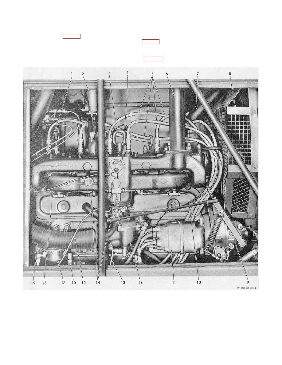
b. The diaphragm-type, engine-driven fuel pump (17, fig. 4-8) is operated by a lobe on the camshaft.. It is
mounted on the side of the
1.
Spark plug
8. Fan guard
14. Primer lines
2.
Overspeed governor
9. Engine speed governor
15. Throttle control cable
3.
Engine lifting eye
10. Governor-to-throttle rod
16. Fuel strainer
4.
Exhaust manifold
11. Magneto
17. Fuel pump
5.
Shielded spark plug cables
12. Carburetor
18. Intake manifold
6.
Exhaust pipe
13. Choke control cable
19. Air intake hose
7.
Radiator hose
Figure 4-8. Left side of engine, identifying components.
4-12
|
|
Privacy Statement - Press Release - Copyright Information. - Contact Us |
