 |
|||
|
|
|||
|
Page Title:
Figure 2-4. Fuel tank and related parts. |
|
||
| ||||||||||
|
|
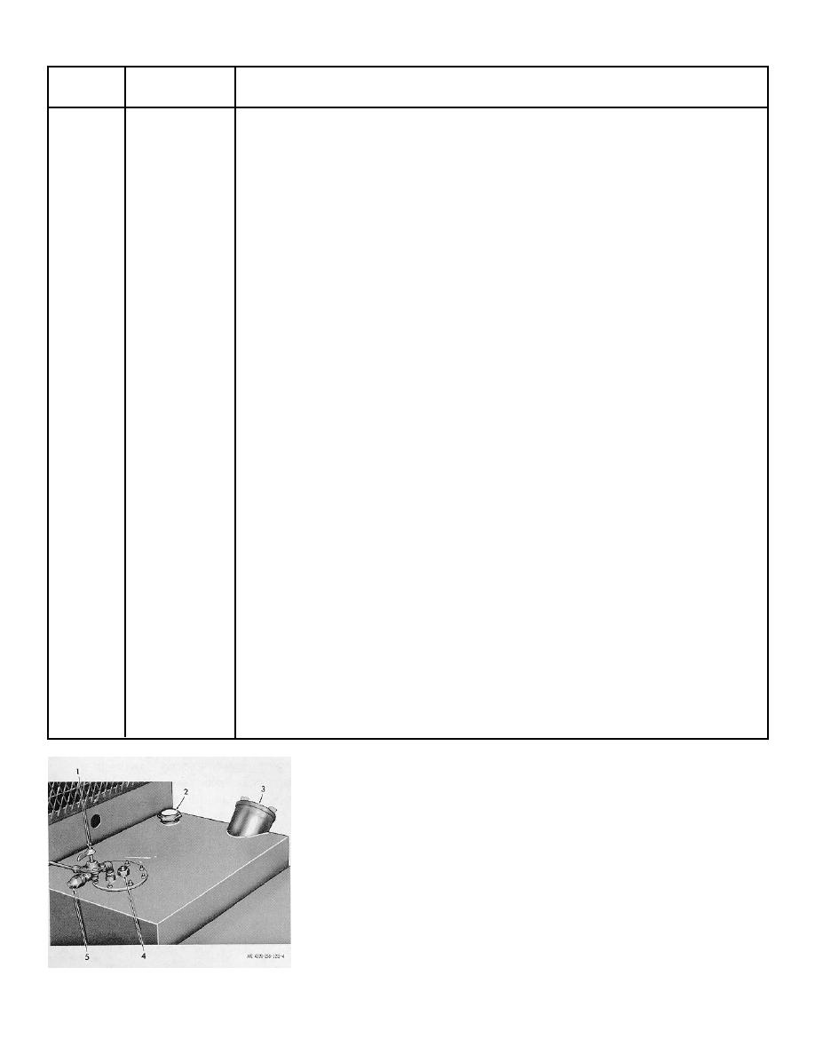 Table 2-1-Continued
Fig. &
index No.
Name
Operation and use
2-2
9
Suction gage
Compound gage indicates either vacuum or pressure condition at suction port when
suction gage valve is open. Indication depends upon specific operating conditions.
2-2
10
Indicates the engine speed in hundreds of rpms. Normal governed speed rating
hourmeter
is 2450 rpm. Engine speed at full load should not go beyond this level. Hour-meter
indicates engine running time based on operating speed (engine revolutions x 100,
000).
2-2
11
Discharge pres-
Indicates pump discharge pressure when discharge pressure gage valve is open.
sure gage
High pressure indicates high discharge head or discharge line restriction. Normal
discharge pressure varies with operating conditions.
2-2
12
Starter push-
When the battery disconnect switch and ignition switch are ON, the starter button
pushbutton, when pressed, energizes the engine starter to turn over the engine for
starting. Safety bypass switch (15) must be held closed during starting to bypass oil
pressure safety switch.
2-2
13
Battery discon-
In the ON position, it closes circuits to the starting system and ignition switch.
nect switch
In the OFF position, it interrupts these circuits.
2-2
14
Ignition switch
In the ON position, it energizes the oil pressure and water temperature gage circuits and
removes the ground from the ignition circuit to permit engine ignition. Battery
disconnect switch must be in ON position to make this switch operative. When moved
to OFF, ignition switch stops the engine by grounding the magneto, regardless of the
position of battery disconnect switch.
2-2
15
Low oil pressure
When pressed, it resets the low oil pressure safety circuit to allow engine starting.
reset
2-3
1
Air eliminator
When open, the air eliminator valve releases air in the discharge piping. Normally
valve
closed during operation after starting.
2-3
2
Air cleaner re-
Indicates red when air cleaner is clogged, preventing free air passage. Requires
striction
reset after air cleaner service.
indicator
2-3
3
Engine primer
When operated, it pumps raw fuel into the intake manifold to facilitate starting.
pump
2-3
7
Suction gage
When open, the suction gage valve applies suction port pressure to suction gage.
valve
2-3
8
Discharge pres-
When open, the discharge pressure gage valve applies discharge pressure to discharge
sure gage valve
pressure gage.
2-4
1
3-way fuel source
This valve has three positions as follows:
selector valve
OFF position shuts off fuel supply to engine.
TANK position opens tank-to-engine fuel supply line.
AUX position opens the line between the auxiliary fuel supply and engine.
2-4
2
Fuel tank gage
Indicates level of fuel in fuel tank
1. Fuel source selector
3. Fuel tank filler cap
valve
4. Autofill connector
2. Fuel tank level gage
5. Auxiliary fuel line
connector
Figure 2-4. Fuel tank and related parts.
2-5
|
|
Privacy Statement - Press Release - Copyright Information. - Contact Us |
