 |
|||
|
|
|||
|
Page Title:
FIGURE 7. DISCHARGE SIDE OF PUMP |
|
||
| ||||||||||
|
|
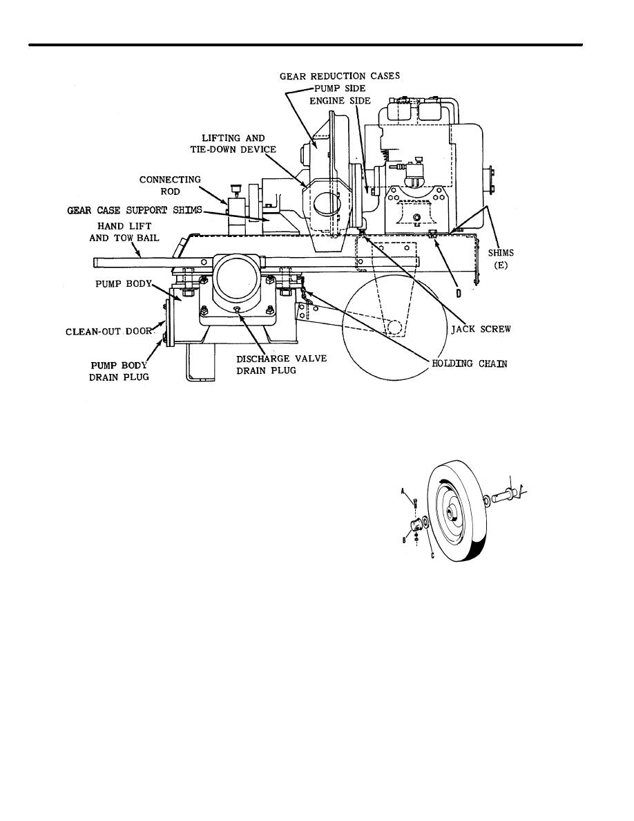 FIGURE 7
DISCHARGE SIDE OF PUMP
24. Wheels (Fig. 8)
The wheels are equipped with a cushion type tire
(non-pneumatic) and contain two sealed type ball
bearings at the hub. Bearings are pregreased and
sealed.
To remove the wheel, remove the 1/4" x 2 1/4"
machine bolt with nut and lock washer (A). Pull off
cap (B) and washer or washers (C). Pull wheel off
axle.
FIGURE 8
WHEEL HUB ASSEMBLY
25. Lifting and Tie Down (Ref. Fig. 7)
Reference for Fig. 8
The diaphragm pump is equipped with two
combination of gravity tion lifting and tie down eyes
A. Machine Bolt w/Nut & L.W.
located at the center of the pump.
B. Cap
C. Washer
12
|
|
Privacy Statement - Press Release - Copyright Information. - Contact Us |
