 |
|||
|
|
|||
|
Page Title:
FIGURE 4. PUMP BODY AND ADJACENT PARTS |
|
||
| ||||||||||
|
|
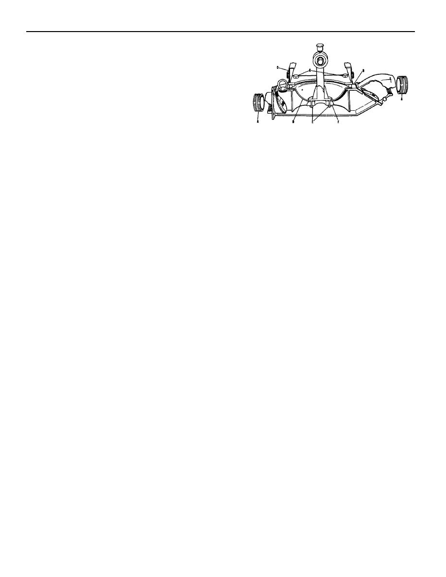 18. Changing The Diaphragm (Fig. 4)
A. With the pump body (B) drained, turn the engine
starting pulley until the connecting rod is in its
lowest position.
B. Remove four bolts and nuts (G)holding pump
body to the frame (C).
C. Lift the combination pump top and frame
upward as far as the holding chain will permit.
The pump top and frame will position over-
center and will be held in position by the holding
chain. (Fig/ 7).
D. The rubber diaphragm (D) is now fully exposed.
E. Remove two 5/8" brass nuts (E) and remove
FIGURE 4
diaphram flange (F).
PUMP BODY AND ADJACENT PARTS
F. Pull old rubber diaphragm (D) off pump. Clean
the inner and outer diaphragm seating areas on
Reference for Fig. 4
pump with a steel brush.
A. 4" Close Nipples
G. Position new rubber diaphragm (D) in place.
B. Pump Body
Replace diaphragm flange (F) and secure with
C. Frame
brass nuts (E). Tighten nuts (E) until diaphragm
D. Rubber Diaphragm
is slightly depressed. Remove preservative
E. 5/8" Brass Nuts
from new diaphragm.
F. Diaphragm Flange
H. Swing the combination pump top and frame
G. Bolts and Nuts
down to its normal position. Secure with the
B. Remove two brass nuts with washers (R) and two
four bolts and nuts (G), taking up a like amount
brass machine screws (K). Washer (L) and weight
on each nut to equalize pressure on the rubber
(P) may be pulled off rubber flap valve (N).
diaphragm edge.
19. Inlet Valve Repair (Fig. 3A)
C. Replace flap valve (N). Assemble items (K) thru(R)
The inlet valve is located at the inlet or suction side of
and place on pump body over the studs. Place
the pump body, and is of the flap valve type.
valve body on pump over studs and secure with the
Depending on use and material pumped, wear will take
5/8 " hex nuts.
place on Item (F), the rubber flap valve. Repair is as
21. Connecting Rod Needle Bearing Repair (Fig. 5)
follows:
A. With the suction line off (disconnected) and
The connecting rod (A) oscilates on the output shaft
pump drained, or if working conditions permit,
(B) of the reduction gearcase. Bearing replacement
suction line may be left on the inlet valve,
is as follows:
remove four 5, %" nuts and washers (V) from
studs (A). Pull inlet valve free from pump body.
A. Remove four bolts and nuts holding pump body
Do not damage gasket (D). Save for reuse.
to the frame. Reference Par. 18.
B. Remove two brass screws (H), and keeper (G).
B. Lift the pump top upward as far as the holding
Save for reuse. Remove two brass screws (C)
chain will permit. Block pump body in this
with nuts and washers (X). Loosen and remove
position and remove rubber diaphragm. Ref.
washer (E) and weight (J).
Par. 18.
C. With new rubber flap valve (F), reassemble flap
C. Remove cap screw (D) and keeper (E). Pull
valve assembly. Replace inlet valve assembly
connecting rod (A) with bearing (C) off shaft.
with gasket (D) on pump body and secure with
D. Press bearing (C) from bore of connecting rod.
the four 5/8" nuts and washers (V) on studs (A).
The grease cup (F) may be cleaned of any hard
20. Discharge Valve Repair (Fig. 3A)
grease that may have accumulated. Repack
The discharge valve is located on the pump body
grease cup. Ref. "Lubrication Chart."
opposite of the inlet valve and is of the flap valve type.
E. Press new bearing (C) into bore of connecting
Depending on use and material pumped, the rubber flap
rod, then hand grease bearing.
valve (N) will have to be replaced. Repair as follows:
F. Replace connecting rod (A) with bearing (C) on
shaft (B). Replace keeper (E) and tighten with
A. Remove four 5/8" hex nuts with washers (Y)
cap screw (D). Hand turn grease cup cap down
from studs (U). Pull discharge valve body (S)
to force grease into bearing and grease channel.
off studs (U).
Refill grease cup to level.
|
|
Privacy Statement - Press Release - Copyright Information. - Contact Us |
