 |
|||
|
|
|||
|
Page Title:
CHAPTER II - PREPARATION BEFORE USE |
|
||
| ||||||||||
|
|
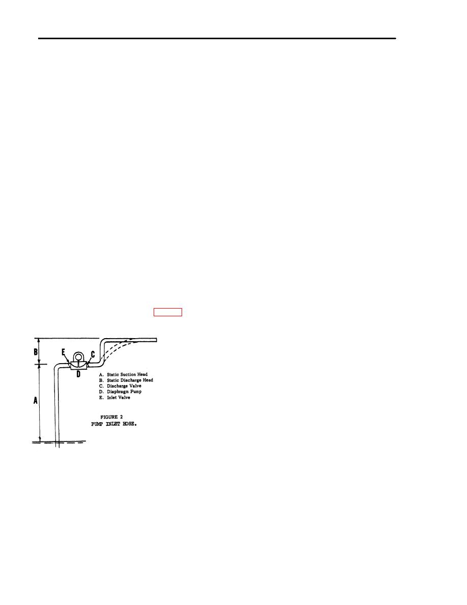 7. Selection and preparation of pump site - The pump
CHAPTER II - PREPARATION BEFORE USE
inlet should not be located higher than 25 feet above
4. Unpacking and inspection - The pump is boxed and
the source of liquid to be pumped. (Fig. 2) The
secured within the box. Upon unpacking, make a
pump is capable of pumping against a total dynamic
visual inspection for any damage or theft in transit.
head of 35' which is a combination of (A) and (B) in
Manuals are contained in a canvas bag for each
Fig. 2, but the Static Suction Head is not to exceed
pump. If pump is to be lifted, see the transportation
25' (measured vertically) above the inlet valve from
data plate (Fig. 1A) for lifting. Lifting "eyes" are
water level. This would leave a 10' Static Discharge
provided on each side of the pump frame. Four 10'
Head (measured vertically).
These figures are
long sections of 4" diameter hose with two 4"
based on using a suction line of same nominal inside
diameter close nipples are contained in one box for
diameter as pump inlet (4"), and one elbow and are
each pump.
calculated at sea level atmospheric conditions.
5. Assembly - The rubber diaphragm has been removed
For maximum pumping efficiency it is recommended
from the pump at the factory and must be reinstalled
that the discharge line be elevated above the height
on the pump before operation. Remove preservative
of the discharge valve. This retains a back pressure
before installation. For installation of the rubber
against the discharge valve on the suction stroke of
diaphragm, refer to Chapter IV, Paragraph 18.
the diaphragm.
Thread the 4" close nipples into the inlet and outlet
Pump should be setting level and as close to the
valves. Nipples (A) must be tight with no air leaks.
liquid to be pumped as possible.
(Reference Fig. 4)
Adequate working space should be provided around
the pump for Inspection and servicing.
The towing bail may be extended or repositioned for
CAUTION: Care should be exercised that the wire
easier hand towing.
reinforced hose is not crimped or flattened as this will
increase priming time and decrease pumping
Suction and discharge hose are connected to the
capacity.
pump at the jobsite.
8. Hose Installation - The suction and discharge hoses
are equipped with Type B1 Rocker Lug Type
6. Lubrication before use - The engine crankcase, pump
Couplings and thread onto the inlet valve and outlet
gearcase and connecting rod bearing grease cup are
valve pipe nipples.
filled to level points at the factory. How-ever, before
The connections are to be threaded tight especially
operation these points should be checked for oil
on the suction side of the pump to prevent air leaks.
levels. Refer to lubrication chart, Page 7, Fig. 9 for
Air leaks will increase priming time and reduce pump
data.
capacity.
A. Suction Hose - The hose connected to the inlet
or suction side of the pump should be of the rigid
type (non-collapsible). Hose should be free of
any breaks, cuts, pin holes or have a collapsed
liner. When the pumping application permits,
the suction line should be kept as short as
possible.
B. Discharge Hose -Hose on the outlet or discharge
side of the pump may be of the collapsible type,
but the rigid type is preferrable.
On long
discharge lines, the line should be one size, and
sometimes two sizes larger than the discharge
fitting of the pump, in order to decrease frictional
loss.
FIGURE 2
9. Movement to new worksite - Disconnect the suction
and discharge hose from the pump. Drain pump body
by removing the pump drain plug, reference, Fig. 7. If
extremely hi-solid content water, mud or mucky water
has been pumped, the pump body should be flushed
out with clean water. The clean-out door may be
removed for this purpose, reference, Fig. 3 and 7.
3
|
|
Privacy Statement - Press Release - Copyright Information. - Contact Us |
