 |
|||
|
|
|||
|
|
|||
| ||||||||||
|
|
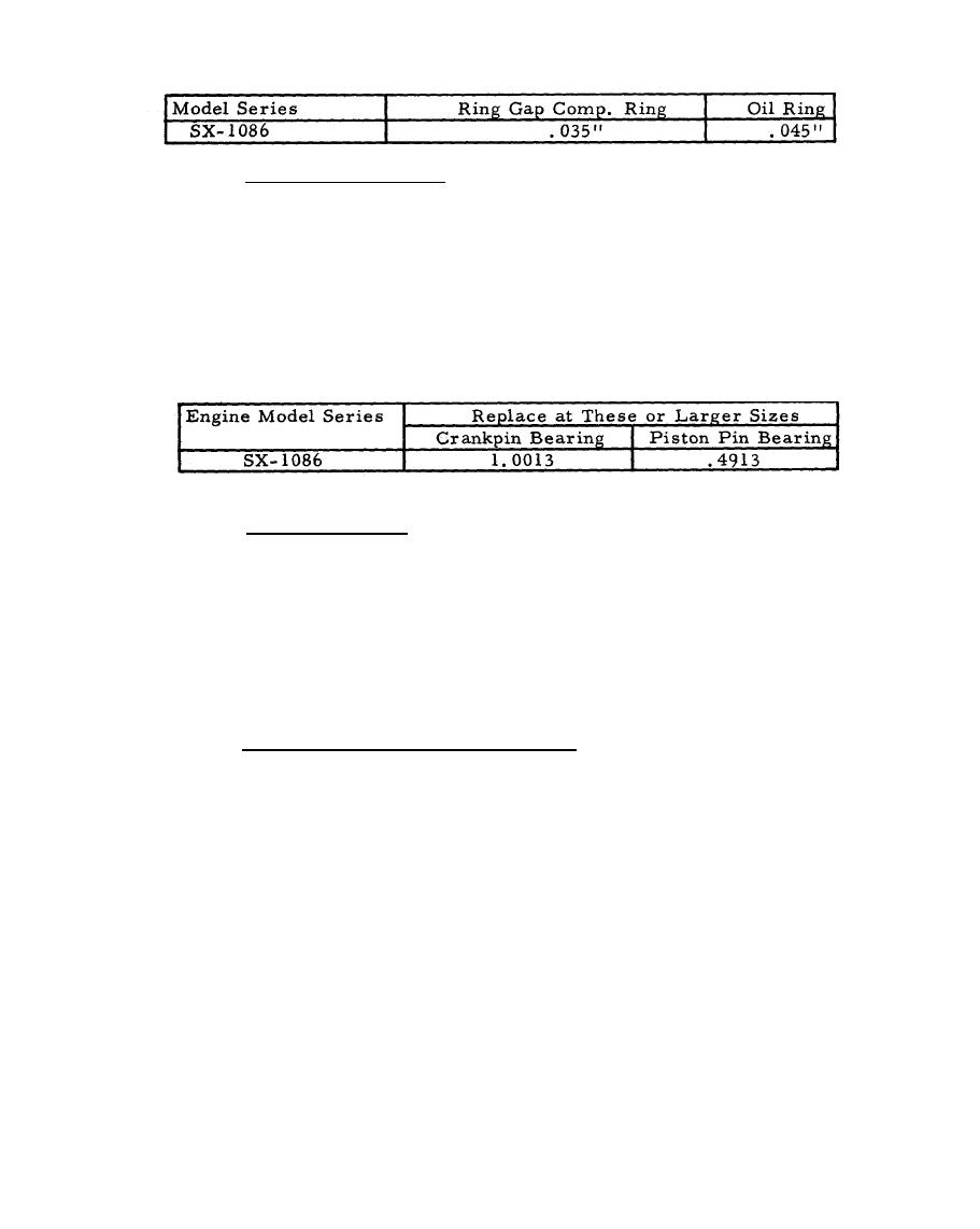 TABLE 6
RING GAP REJECTION SIZE
Check Connection Rod,
5.2.2.7.5
If the crankpin bearing in the rod is scored, the rod must be replaced.
Rejection sizes of crankpin bearing hole and piston pin bearing hole are
shown in Table No. 7. Piston. pins .005" oversize are available in case
the connecting rod and piston are worn at the piston pin bearing. If, how-
ever, the crankpin bearing in the connecting rod is worn, the rod should
be replaced. Do not attempt to "file" or "fit" the rod.
TABLE 7
CONNECTING
ROD
5.2.2.7.6
Check Piston Pin.
If the piston pin is worn .0005" out of round or below the rejection sizes
listed below, it should be replaced. Table No. 8.
5.2.2.7.7
Assemble Piston and Connecting Rod.
This piston pin is a push fit in both piston and connecting rod. On models
using a solid piston pin, one end is flat, the other end is recessed. Other
models use a hollow pin.
Place a pin lock in the groove at one side of the piston. From the opposite
side of the piston, insert the piston pin, flat end first with solid pin, either
end with hollow pins, until it stops against the pin lock. Use a thin nose
pliers to assemble the pin lock in the recessed end of the piston. Be sure
the locks are firmly set in the grooves.
64
|
|
Privacy Statement - Press Release - Copyright Information. - Contact Us |
