 |
|||
|
|
|||
|
Page Title:
Section XI. ROCKER ARM ASSEMBLIES AND PUSH RODS |
|
||
| ||||||||||
|
|
 Section XI. ROCKER ARM ASSEMBLIES AND PUSH RODS
7-33. General
b. Remove and install the rocker arm assemblies
The rocker arm assemblies are mounted on top of the
and push rods as shown in figure 7-11.
cylinder heads, shielded under the rocker arm covers.
c. Disassemble the rocker arm assembly, as shown
The push rods are vertically positioned in openings on the
in figure 7-12, in the sequence indicated by the key
left side of the engine. When engine is operating, the
numbers. Reassemble in reverse sequence.
push rods are moved up and down by the revolving cams
on the camshaft. This movement is transmitted by the
rocker arms to the intake and exhaust valves, causing
7-35. Cleaning, Inspection, and Repair
them to open and close in correct timing with the positions
of the pistons. The rocker arm shafts are made of steel
tubing, drilled to carry oil under pressure to each rocker
b. Adjust the valves after installation of the rocker
arm.
arm assemblies (para 3-36).
7-34. Disassembly and Reassembly
a. Remove and install the rocker arm covers as
shown in figure 3-9.
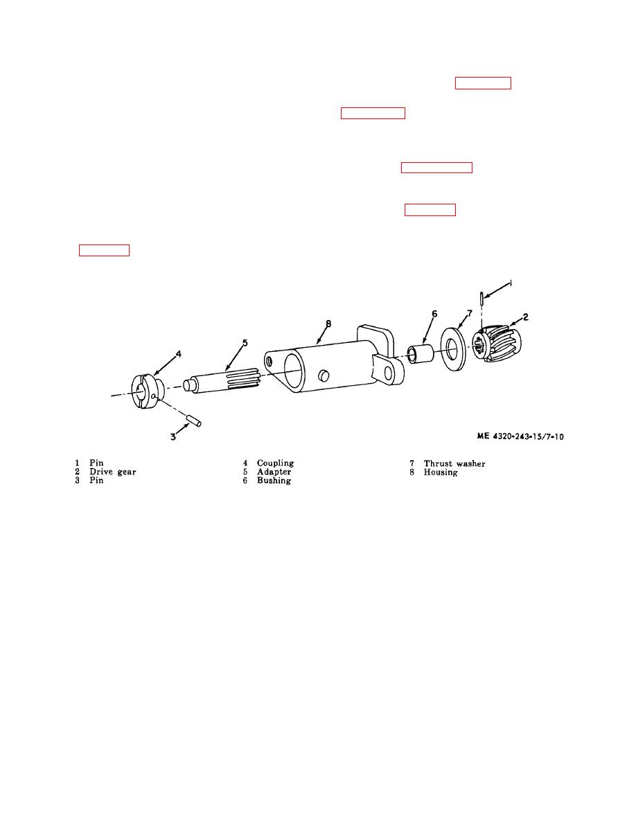
Figure 7-10. Tachometer drive housing, disassembly and reassembly.
7-16
|
|
Privacy Statement - Press Release - Copyright Information. - Contact Us |
