 |
|||
|
|
|||
|
|
|||
| ||||||||||
|
|
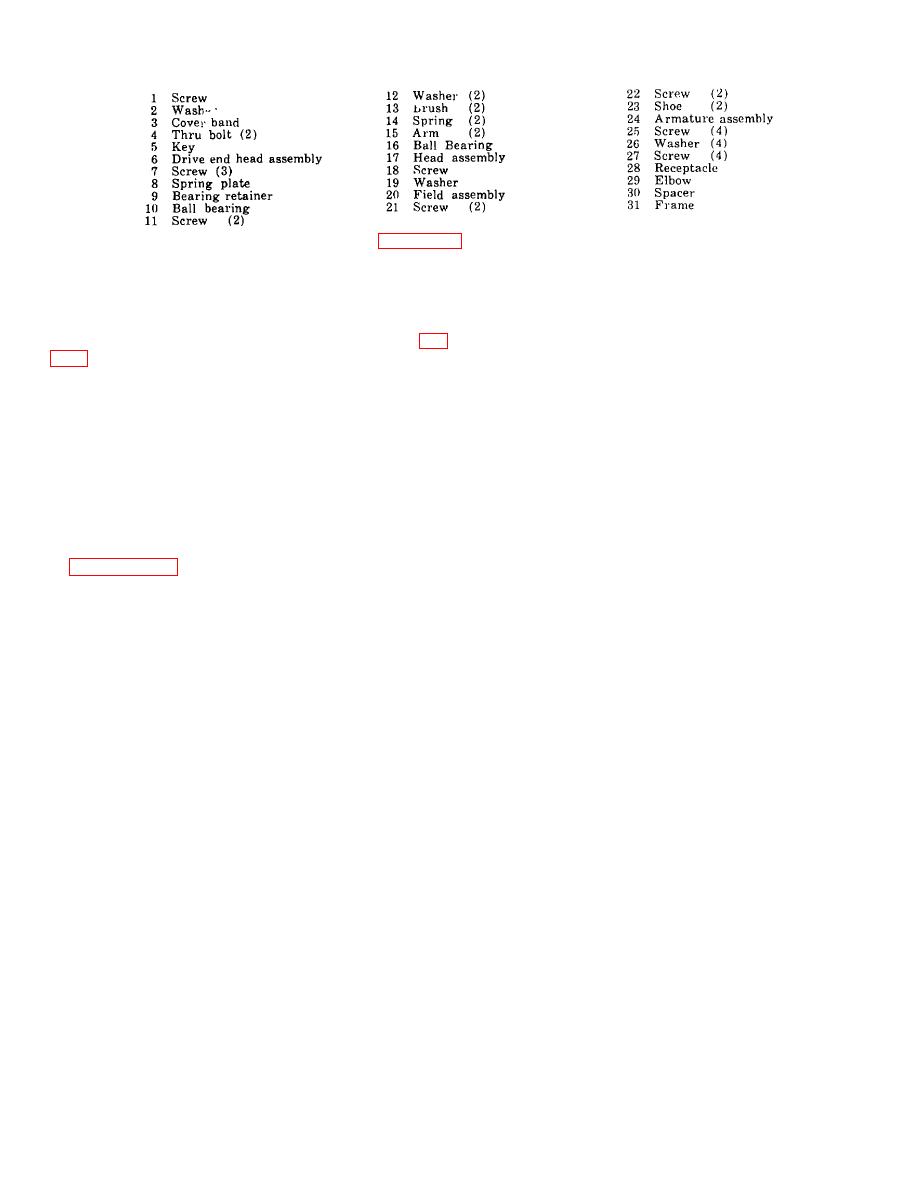 Figure 7-4-Continued.
Section V. GENERATOR REGULATOR
and the regulator connector. Connect another jumper
7-12. General
between pin "B" of the regulator connector and ground.
The three-unit, battery-charging generator regulator (fig.
Start the engine and slowly increase the speed. No
increase in the charging rates indicates the generator is at
keep the batteries fully charged. The circuit-breaker unit
fault. An increase indicates that the regulator is at fault
closes the circuit between the batteries and the generator
and must be adjusted or replaced.
when the generator voltage is higher than the battery
Caution
voltage, and opens the circuit when the battery voltage
equals that of the generator. The current-regulator unit
Never remove the cover from the
limits the current to the maximum rated value of the
voltage regulator while the engine is
generator. The voltage regulator limits the voltage to the
operating
or
the
battery
is
maximum rated value of the system at full charge.
connected.
7-13. Removal and Installation
7-15. Cleaning
Remove and install the Generator Regulator as directed
Do not disassemble the regulator under any
circumstances. Remove cover and wipe assemblies,
insulation, capacitors, and resistors with a clean rag,
7-14. On-Engine Testing
slightly dampened in gasoline, paint thinner, or
Defects in the battery-charging generator system are
drycleaning solvent.
indicated by a high charging rate when the batteries are
7-16. Testing
fully charged. Perform the on-engine testing as follows:
a. With test probes, touch "Arm" Terminal and
a. When a high-charging rate with fully charged
circuit breaker stationary contact. (Touch end of series
batteries is indicated, disconnect the lead assembly
winding and circuit breaker stationary contact on
connector from the regulator (fig. 320) and connect a
regulators which do not have the terminals directly on the
jumper between pin "A" of the lead assembly connector
sub-base.) If lamp does not light, it indicates an open
and pin "A" of the voltage regulator connector. Operate
circuit in one of the series coils or connections. Inspect to
the unit at half throttle. If the output remains high, the
find cause of open and repair or replace parts affected.
fault is in the generator or wiring. If the output drops off,
the trouble is in the regulator and it must be adjusted or
b. Touch test probes to "Arm" and "Bat" terminals.
replaced.
(Touch end of series winding end circuit breaker yoke on
regulators which do not have the terminals directly on the
b. When a low, or no-charging rate with partially or
subbase.) If lamp lights, install new circuit breaker
fully discharged batteries is indicated, inspect for loose
contacts or complete circuit breaker. unit.
connections or damaged wiring. If no faults are found,
disconnect the connector as in (1) above. Connect two
c. Touch test probes to "Field" and "Arm"
jumpers between the pins of the lead assembly connector
7-7
|
|
Privacy Statement - Press Release - Copyright Information. - Contact Us |
