 |
|||
|
|
|||
|
|
|||
| ||||||||||
|
|
 TM 5-4320-243-15
(4) Continue to rotate the engine until the
flywheel timing mark is aligned as shown in figure 3-25.
(5) Install the magneto and gear as shown by
as shown by figure 3-25.
(6) Install the spark plug in the number 6
cylinder and install the timing cover plug(fig. 3-25).
(7) Follow the instructions in d below and
time the engine.
d. Ignition Timing
(1) Connect the ignition timing light to the
number 6 sparkplug lead and to the 24-volt power
source.
(2) Start the engine and let it idle
(3) Point the timing light through the timing
hole in the flywheel housing. If the timing is correct, the
flywheel timing mark (fig. 3-25) will be in line with the
pointer inside the flywheel housing each time the light
flashes.
(4) To correct faulty timing, loosen the
magneto clockwise and counterclockwise until timing is
correct. Tighten the magneto mounting screws.
3-50. Spark Plug Leads and Spark Plugs
a. Remove and install the spark plug leads and
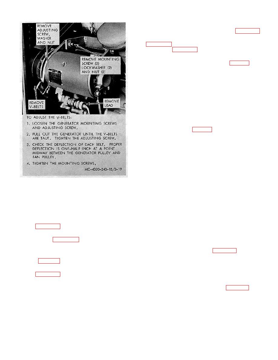
Figure 3-19. Generator, bracket and adjustment
spark plugs as shown in figure3-26.
strap,
Caution: Do not pull on the cable or twist the
braided shielding.
b. Refer to figure 3-22, and perform the on-
equipment test.
b. Clean and check the gap between the spark
plug electrodes with a wire feeler gage. The correct gap
3-49. Magneto
is 0.030 inch. If necessary, regap the electrodes,
a. Adjustment. Adjust the magneto contacts as
carefully bending the ground electrodes until the proper
shown by figure 3-23.
gap is established.
b. Removal. Remove the magneto and magneto
3-51. Batteries, Cable and Box
gear as shown by figure 3-24. Clean and inspect.
a. Remove and install the battery cover, batteries,
c. Installation.
and battery cable as shown in figure 2-1, in sequence
(1) Remove the spark plug from the number
indicated by key numbers.
6 cylinder (para 3-50).
b. Remove and install the battery box by removing
(2) Make the timing marks accessible as
four screws and lockwashers holding the battery box to
shown by figure 3-25.
the skid.
(3) Place the thumb over the spark plug hole.
c. Test and service battery as directed in daily
Rotate the engine until air pressure is felt, indicating the
preventive maintenance services chart, figure 3-4.
compression stroke.
3-27
|
|
Privacy Statement - Press Release - Copyright Information. - Contact Us |
