 |
|||
|
|
|||
|
|
|||
| ||||||||||
|
|
 TM 5-4320-243-15
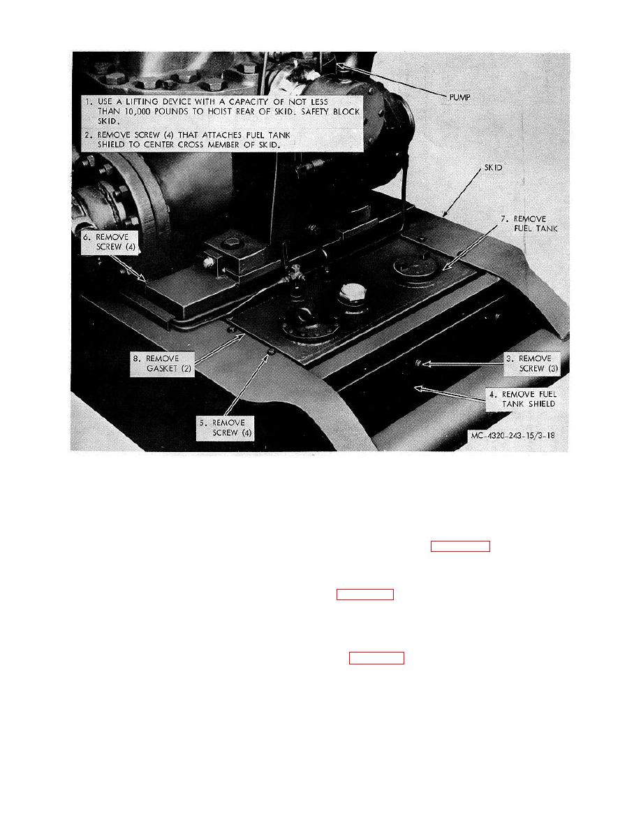
Figure 3-18. Fuel tank shield and fuel tank, removal and installation.
Section XI. ELECTRICAL SYSTEM
3-45. General
The 24-volt electrical system consists of two 12-volt
3-46. Generator
batteries in series, the battery box, generator, magneto,
Remove and install the generator, following the
starting motor, generator regulator, spark plugs, and the
sequence shown by figure 3-19.
wiring and switches required to connect and operate
these components. The starter motor is a 24-volt,
3-47. Generator Regulator
series-wound dc motor powered by the 24-volt generator
Remove and install the generator-regulator as shown by
driven by two V-belts. The generator charging rate is
controlled by the generator regulator which is mounted
on the front engine support. The magneto furnishes the
3-48. Starting Motor and Solenoid
high-voltage ignition current via the ignition wires to the
spark plugs.
and lead assembly in sequence shown by key numbers
Caution: Always remove the battery ground
in figure 3-21.
cable before working on the engine electrical system.
3-26
|
|
Privacy Statement - Press Release - Copyright Information. - Contact Us |
