 |
|||
|
|
|||
|
Page Title:
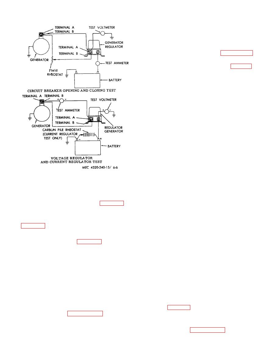
Figure 6-6. Generator regulate test set-up. |
|
||
| ||||||||||
|
|
 b. Removal. Refer to figure 3-25 and remove the
magneto.
c. Cleaning and Inspection. Refer to paragraph 3-
46e and clean and inspect the magneto.
d. Disassembly.
Refer
to
and
disassemble the magneto.
e. Cleaning Inspection and Repair. (fig. 3-26)
(1) Clean the housing, gaskets, and
preformed packing, and distributor block with a wet
soapy cloth. Rinse and wipe dry.
(2) Clean all metal parts except bearings in
an approved cleaning solvent; dry with clean, dry
compressed air.
(3) Clean bearings by placing in a strainer
and dipping in a clean solution of cleaning solvent.
Flush until clean.
Caution
Do not spin balls or needles when
bearings are without lubricant.
Keep bearings covered so dirt and
dust will not enter.
(4) Repack bearings with clean bearing
grease. Inspect bearings for smooth rotation without
Figure 6-6. Generator regulate test set-up.
rough or catchy spots. Inspect races, balls, and needles
for wear or damage. Replace damage bearings.
age. With the generator operating at approximately
(5) Clean the electrical parts with a cloth
3,000 rpm and the generator operating temperature,
dampened in an approved cleaning solvent.
note the operating voltage. It must be 27.5 to 29.5 volts
as indicated on the voltmeter. Refer to figure 6-4 and
(6) Inspect the electrical parts for corrosion,
adjust the voltage if necessary.
cracks, breaks, frayed insulation, damaged terminals, or
evidence of failures. Replace if damaged or defective.
(7) Connect the generator regulator as shown
(7) Inspect the spring for wear, cracks,
in figure 6-5 using the carbon pile rheostat. Check the
damage, or loss of tension; replace if damaged or
operating amperage of the current regulator. It should
deformed.
operate at 16 to 20 amperes. If it fails to operate within
the required range, refer to figure 6-4 and adjust the
(8) Inspect gear teeth for chips, breaks, wear,
current setting. After each change of adjustment,
or damage; replace if damaged.
(9) Test
the
on
a
standard
return to speed and read current.
condenser tester.
(8) If the adjustment cannot be made, replace
(10) Inspect all other parts for cracks, breaks,
the generator regulator.
wear, or other damage. Replace if damaged.
c. Replacement. Refer to figure 3-21 and replace
f. Assembly.
Assemble the magneto in the
the generator regulator.
reverse order of disassembly.
6-6. Magneto
g. Timing and Installation.
Time and install the
magneto (para 3-45g).
67. Radiator
description.
6-7
|
|
Privacy Statement - Press Release - Copyright Information. - Contact Us |
