 |
|||
|
|
|||
|
|
|||
| ||||||||||
|
|
 order of disassembly.
6-4. Starting Motor
a. General.
Refer
for
description.
b. Removal.
Refer to figure 3-22 and remove
starting motor.
c. Cleaning and Inspection. Refer to paragraph 3-
45e and clean and inspect the starting motor.
d. Testing. Connect the starting motor in a test
circuit as shown in figure 6-3. Adjust the starting motor
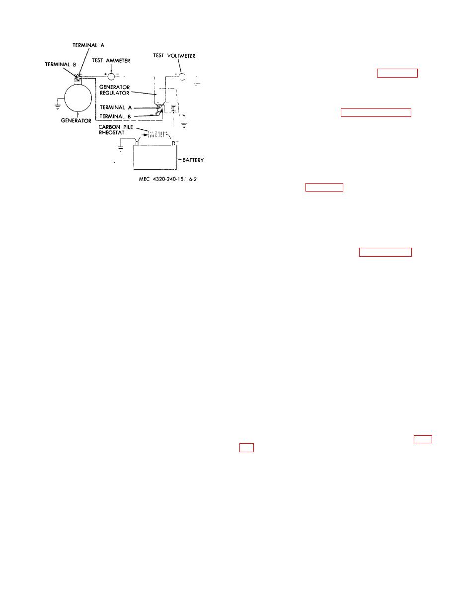
Figure 6-2. Generator test circuit.
voltage draw to 23.5 volts by adjusting the variable
resistance. With the starting motor operating with a
(7) Check for open circuits by inspecting for
voltage draw of 23.5 volts, the speed should be between
loose connections at the points where the conductors
5,800 and 6,800 rpm and the current draw should be 33
are connected to the commutator risers. Open circuits
amperes. If speed is not within limit or the current draw
can be checked electrically by determining if continuity
is not 33 amperes, repair or replace the motor.
exists between adjacent commutator bars. If the bars
e. Disassembly.
Refer to
and
are not badly burned, resolder the leads and turn the
disassemble the starting motor.
commutator down on a lathe. Undercut the mica and
test for short circuits as described in subparagraph (6)
f. Cleaning, Inspection, and Repair.
above. If the open circuit cannot be corrected replace
the armature.
(1) Clean the armature and field frame
(8) Check for grounds by checking the
assembly with a cloth lightly dampened in an approved
armature with a test lamp. Place one probe of the test
cleaning solvent.
lamp on the armature core and the other on each
(2) Clean all other parts of the starting motor,
commutator bar in turn. If the test lamp lights, the
except the brushes, in an approved cleaning solvent; dry
armature is grounded. If grounded, clean it thoroughly
thoroughly with compressed air.
and recheck for grounds. If ground cannot be corrected,
replace the armature.
(3) Check the size of the brushes; replace
them if they are less than 3/8 of an inch long.
(9) Check the field coils for grounds by
checking the coils with a test lamp. Place one probe of
(4) Inspect the armature commutator for
the test lamp on the field frame assembly and the other
roughness, out-of-round or high mica. If any of these
on the field coil leads. If the test lamp lights, the field
conditions exist, turn the commutator down on a lathe
coils are grounded. Replace the field coils if a ground is
and undercut the mica 1/32 inch. Remove only enough
indicated.
stock to make the commutator smooth and round. After
undercutting, finish the commutator with No.
00
(10) Check the field coils for open circuits by
sandpaper. Clean all particles off commutator using
checking with a test lamp. Connect the probes of the
compressed air. Check armature for short circuits (para
lamp to the two leads from the coils. If the lamp does
not light, the coil is open. Replace the field coils if the
circuit is open.
Caution
Always blow particles off the
commutator in the direction away
from the armature windings.
(5) Check the brush holders for distortion,
cracks, breaks, or other damage; replace damaged
brush holders.
6-3
|
|
Privacy Statement - Press Release - Copyright Information. - Contact Us |
