 |
|||
|
|
|||
|
Page Title:
Muffler and Exhaust Pipe |
|
||
| ||||||||||
|
|
 e. Installation. Install muffler in reverse order
described above.
Note. Make sure there is at least 1 inch clearance
between muffler and muffler guard.
3-80. Manifolds
a. General. The manifold consists of two duct works,
the intake and exhaust. The intake manifold is arranged
to give an equal quantity of a gasoline and air mixture,
to each cylinder. The exhaust manifold is routed so as
to heat the intake manifold and discharge the exhaust
gases from each cylinder to a common outlet.
b. Inspection. Inspect for leaks, cracks, and missing
or loose parts.
c. Removal.
(1) Refer to paragraph 3-79d and remove the
muffler.
(2) Refer to figure 3-10 and remove carburetor.
(3) Refer to figure 3-17 and disconnect the fuel
primer lines.
(4) Refer to figure 3-59 and remove manifold.
d. Installation. Install the manifolds in reverse order
of removal.
3-81. Housing Assembly
a. General. The engine is enclosed in a sheet metal
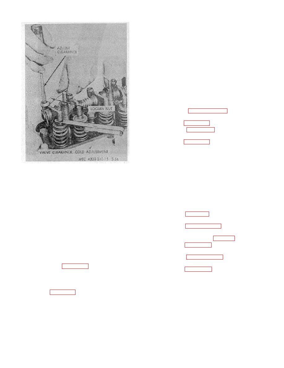
Figure 3-56. Valve clearance adjustment.
housing. The two side panels are removable to provide
access to the engine and its components.
The
just starts to open on cylinder number 1, adjust valve
instrument panel is mounted at the rear end of the
tappets on cylinder number 4.
engine, in which are mounted the controls and
(4) Check to be sure all locknuts are secure.
instruments necessary to run the pumping unit. The
Inspect valve retainers, spring, and rocker arms for
instrument panel is covered by an access door.
wear.
b. Removal.
d. After valves are adjusted install all parts removed
(1) Refer to figure 8-1 and remove lifting bail by
in reverse order as described above.
removing nuts (9) and lockwashers (8).
3-79. Muffler and Exhaust Pipe
(2) Refer to paragraph 3-79d and remove muffler
a. General. The muffler is mounted on top the
guard and muffler.
housing, and is covered by a muffler guard. The
(3) Remove side panels. (fig. 3-60).
purpose of the muffler is to muffle exhaust sound and to
(4) Refer to figure 3-60 and remove capscrews (7),
prevent any sparks from reaching the open air.
lockwashers (8), and hood (9).
(5) Refer to paragraph 3-50b(6) and remove fan
leaks, cracks, dents, missing or loose parts.
guard.
(6) Refer to figure 3-60 and remove capscrews (11
deposits.
& 20), lockwashers (12 & 19), and sides (10 & 18).
d. Removal.
(1) Refer to figure 3-57 and remove muffler guard.
(2) Refer to figure 3-58 and remove muffler.
3-47
|
|
Privacy Statement - Press Release - Copyright Information. - Contact Us |
