 |
|||
|
|
|||
|
|
|||
| ||||||||||
|
|
 T M 5-4320-237-15
other damage.
(7) Inspect all other parts for cracks, dis-
(4) Inspect the governor thrust sleeve
tortion, wear, and other damage; re-
for cracks, wear, and scoring.
place all damaged parts.
(5) Inspect the governor flyweights for
c. Reassembly and Installation.
worn mounting holes and for worn
(1) Reassemble the camshaft and gover-
-
t h r u s t pins.
nor in reverse of the numerical se-
(6) Inspect the governor yoke and shaft
quence as illustrated in figure 47.
for a worn shaft and yoke, bent
shaft, and worn or damaged threads.
(2) Install the crankshaft (para 98).
Section VII. CRANKCASE
101. General
102. Crankcase
The crankcase is an integral unit which in-
a. Removal.
eludes the cylinder block and the crankshaft
(1) Remove the valves (para 92).
housing. The cylinder block portion of the
(2) Remove the engine base and oil
unit is deeply finned to promote mm-e rapid
pump (para 94).
dissipation of the heat generated during the
(3) Remove the piston and connecting
operation of the engine. The crankcase is pro-
rod (para 96).
vided with valve guides which are pressed in-
(4) Remove the crankshaft (para 98).
(5) Remove the camshaft and governor
insert is peened into the crankcase.
b. Cleaning and Inspection.
(1) Clean the crankcase with an approved
cleaning solvent; dry thoroughly.
(2) Inspect the cylinder bore for cracks,
warping, worn or scored cylinder
walls, broken cooling fins, worn or
damaged threads, and other damage.
Replace a damaged crankcase.
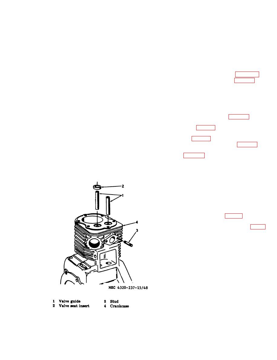
(3) Check the fit of the valves in the
valve guides. If it is not within the
tolerances listed in table 1, drive out
the valve guides and replace them
with new guides as shown in figure
48.
(4) Check the exhaust valve seat insert
for distortion, cracks, looseness, and
pitting. If necessary, replace the in-
sert as follows:
(a) Use a puller to remove the insert
from the exhaust valve opening.
(b) Clean all carbon out of the insert
counterbore in the cylinder block.
and clean the valve stem guide bore.
(c) Finish the counterbore in the cylin-
der block to provide the correct
bore-to-insert clearance. Chill the
insert with dry ice and, using a pi-
lot driver, tap the insert into place
|
|
Privacy Statement - Press Release - Copyright Information. - Contact Us |
