 |
|||
|
|
|||
|
Page Title:
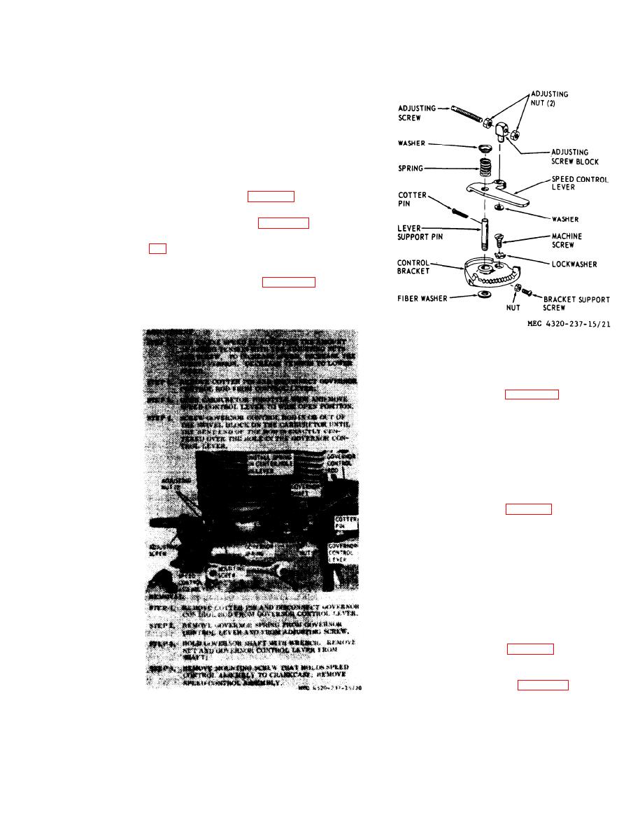
Governor Linkage and Speed Control |
|
||
| ||||||||||
|
|
 TM 5-4320-237-15
to make sure they operate freely
without binding.
(3) Inspect the governor control rod for
distortion, wear at bearing points, or
other damage.
mounting
(4) Inspect the carburetor
damaged
for looseness,
studs
threads, or other damage. Replace
any damaged parts.
assemble the carburetor.
stall the carburetor. Adjust as shown in fig-
ure 17.
just engine speed. Engine speed with pump
under load should be 2750 to 2850 rpm.
reassembly.
move governor linkage and speed control.
Caution: Never attempt to operate the en-
gine or pumping unit with the governor link-
age disconnected. This may cause overspeed-
ing of the engine, resulting in severe engine
damage.
assemble speed control.
d. Cleaning and Inspection.
(1) Clean parts with an approved clean-
ing solvent; dry thoroughly.
(2) Inspect all parts for cracks, distor-
tion, wear at bearing points, or other
damage; replace damaged parts.
assemble speed control assembly.
stall speed control assembly and gown-nor
linkage.
adjustment, removal and installation.
|
|
Privacy Statement - Press Release - Copyright Information. - Contact Us |
