 |
|||
|
|
|||
|
|
|||
| ||||||||||
|
|
 TM 5-4320-234-34
gear set marked the same as the set you removed.
cm) feeler gage into the gap between the gears. If the
gage will enter, the clearance is excessive.
Check the clearance as directed in (4) above. If
clearance is too great, install the next smaller size gear
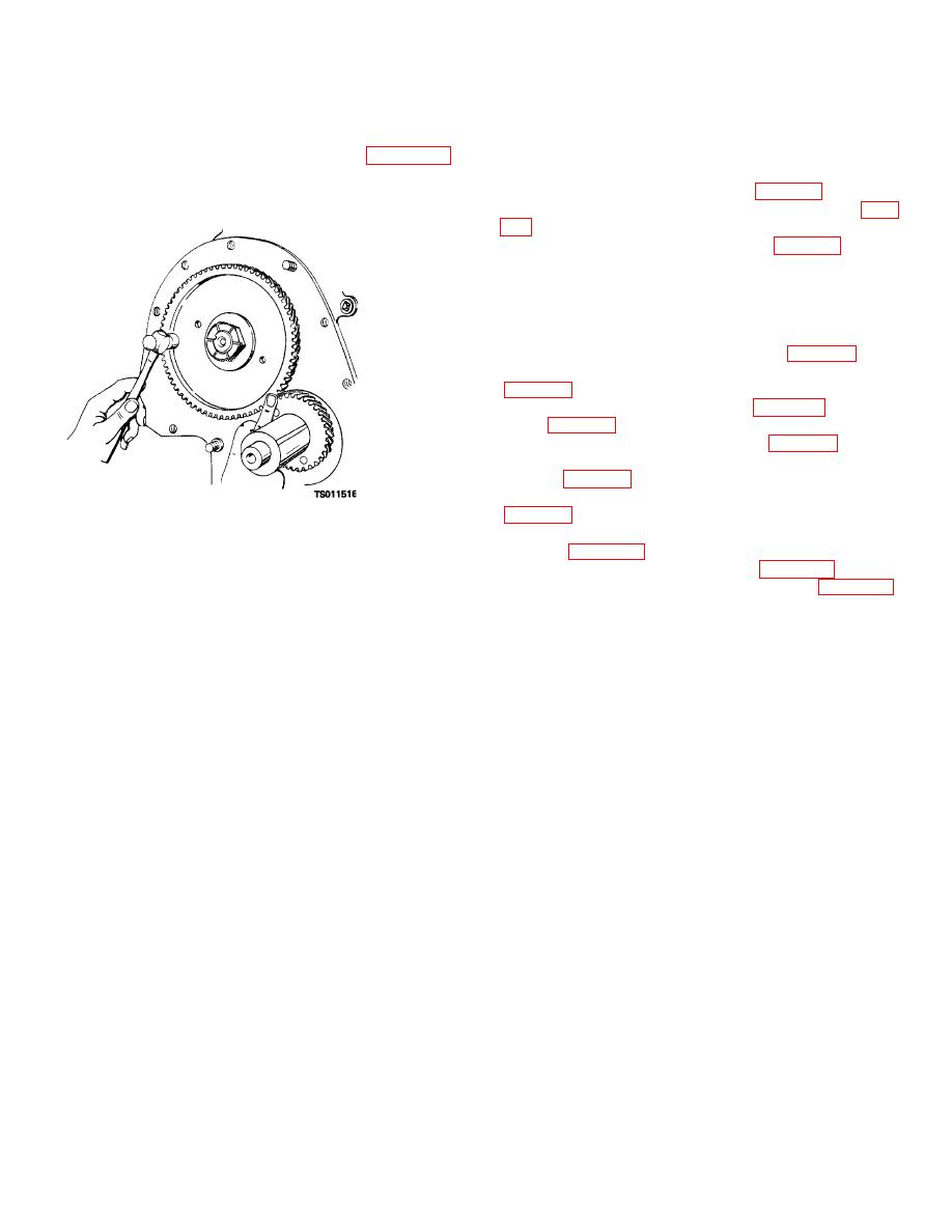
(b) If the gage will not enter, place a finger
at the junction of the two gears as shown in figure 4-20
set. If clearance is insufficient, install the next larger
size set.
and tap the camshaft gear with a hammer. If vibrations
(6) Install the gear cover (para 4-7c).
can be felt in the large gear, the clearance is sufficient.
(7) Install the valves and valve tappets (para
(8) Install the cylinder head (para 4-3c).
4-12. Cylinder Block
a.
Removal and Disassembly.
With the engine
mounted on an engine overhaul stand, proceed as
follows:
(1) Remove the cylinder head (para 4-3a).
(2) Remove the intake and exhaust valves
(3) Remove the oil pan (para 4-5a) and oil
pump (para 4-6a).
(4) Remove the gear cover (para 4-7a).
(5) Remove the flywheel and flywheel
housing (para 4-8a).
(6) Remove the pistons and connecting rods
(7) Remove the crankshaft and main
Figure 4-20. Checking for insufficient timing gear
bearings (para 4-10a).
clearance.
(8) Remove the camshaft (para 4-11a).
(9) Remove the oil gage rod (1, fig. 4-21)
(5) If gear clearance is too great or too
from the cylinder block, and remove the oil filler cap (3)
small, the gears must be replaced. Replace the gears
from the oil filler nipple (4). If the oil gage rod support
only in sets. Gear sets are available in standard size
(2) or oil filler nipple is damaged, pull these parts from
(marked S), 0.002 (0.0050 cm) and 0.004-inch (0.0100
the cylinder block.
cm) undersize (marked U), and 0.002 (0.0050 cm) and
0.004inch (0.0100 cm) oversize (marked 0). Install a
4-20
|
|
Privacy Statement - Press Release - Copyright Information. - Contact Us |
