 |
|||
|
|
|||
|
Page Title:
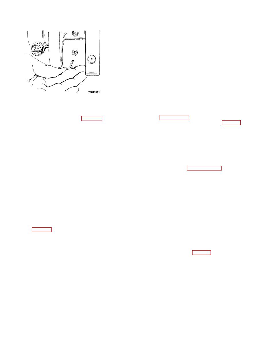
Figure 4-15. Removing upper bearing shell with angular pin. |
|
||
| ||||||||||
|
|
 TM 5-4320-234-34
(4) Inspect the bearing shells for cracks and
scoring. New bearings are smooth and highly polished.
After a few hours of operation, the bearing surfaces
become leaden grey in color and develop minute craters
which give the bearing surfaces an almost cellular
appearance. This is a natural characteristic of the
bearing and does not indicate bearing failure. Replace
bearings if they are scored or damaged. Check the
bearing thickness with a ball micrometer. Check several
locations on the bearing. If thickness is less than 0.0920
inch (0.2300 cm), replace the bearing.
(5) Inspect the bearing caps for cracks and
distortion and for burrs and gouges of the seating
surfaces. Clean up any burrs with a fine stone to ensure
proper seating of the bearing cap on the block.
Figure 4-15. Removing upper bearing shell with
c. Reassembly and Installation.
angular pin.
(1) Install the rear oil seal and oil guard as
directed in paragraph 4-5c.
(7) Pull the gear (21, fig. 4-13) from the
(2) Position the thrust plate (23, fig. 4-13) on
crankshaft (36). Remove the key (22) and the thrust
the crankshaft and install the key (22) in the keyway of
plate (23).
the crankshaft, after you make sure that the keyway is
b. Cleaning and Inspection.
free of burrs. Press the gear (21) onto the crankshaft.
WARNING
CAUTION
Clean all parts in a well-ventilated area.
When you install the crankshaft, make sure
Avoid inhalation of solvent fumes and
that you aline the timing marks on the
prolonged exposure of skin to cleaning
crankshaft with the timing marks on the
solvent. Wash exposed skin thoroughly.
camshaft gear. See paragraph 4-11.
Dry cleaning solvent (Fed. Spec. P-D-680)
used to clean parts is potentially dangerous
(3) Position the upper half of the main
to personnel and property. Do not use near
bearings (27, 30, 33, and 35) in the seats in the
open flame or excessive heat. Flash point of
crankcase. Position the crankshaft in the bearing shells.
solvent is 100 F. to 138 F. (38 C. to 59 C.).
(4) Install the lower half of the main bearings
into the bearing caps (25, 29, 32, and 34).
(1) Clean all parts with cleaning solvent (Fed.
(5) Check the clearance between the
Spec. P-D-680). Clean oil passages in the crankshaft
crankshaft bearing journals and bearings as follows:
with a rifle cleaning brush. Make sure all passages are
(a) Place a piece of plastigage near the oil
open.
hole of the bearing cap.
(2) Inspect the crankshaft for cracks, worn or
(b) Position the cap on the block and
scored journals, damaged threads, and burred keyways.
secure with the two screws and lockwashers. Tighten
Refer to table 4-1 for wear limits. If magnetic particle
the screws to 85 to 95 foot-pounds (11.75 to 13.13 kgm)
inspection equipment is available, you should use it to
check the crankshaft for hidden flaws. Replace a
(c) Remove the bearing and bearing cap.
damaged crankshaft.
Check the bearing journal-to-bearing clearance
(3) Inspect the gear for cracked, chipped and
indicated by the plastigage (fig. 4-16).
broken teeth; replace a damaged gear.
4-17
|
|
Privacy Statement - Press Release - Copyright Information. - Contact Us |
