 |
|||
|
|
|||
|
Page Title:
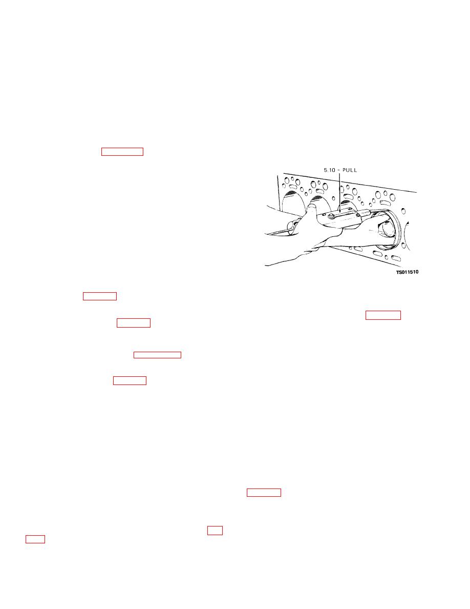
Figure 4-14. Checking piston fit in cylinder bore. |
|
||
| ||||||||||
|
|
 TM 5-4320-234-34
stock cut 1/2 inch wide. Dress the edges of the feeler
CAUTION
stock with a stone to remove burrs and feathered edges.
When you push the piston and rod from the
The block and pistons must be at room temperature
block, be careful the connecting rod does
when you check the piston fit. Position the feeler stock
not scratch the cylinder wall.
midway between the piston pin bosses. With the piston
(5) Push assembled piston (18), rings (17),
inserted about 2 inches into the block, the feeler stock
and connecting rod (20) up through the top of the block.
must pull from the block with 5 to 10 pounds pull. If the
NOTE
feeler stock does not offer enough resistance, perform
Disassemble the pistons and piston rods in sets, and
the same test with a new standard size piston. If
keep the sets together. Also, be sure that you install each
piston and piston rod set into the cylinder from which it
sufficient resistance is still not obtained, the cylinders
was removed.
are worn oversize, and the block must be replaced.
(6) Refer to figure 4-13 (items 15 through 20)
and disassemble the piston and connecting rod.
b. Cleaning and Inspection.
WARNING
Dry cleaning solvent, P-D-680 or P-S-661,
used to clean parts is potentially dangerous
to personnel and property. Avoid repeated
and prolonged skin contact. Do not use
near open flame or excessive heat. Flash
point of solvent is 100 F.138 F. (38 C.-59 C.).
(1) Discard and replace the piston rings.
(2) Clean all parts with cleaning solvent (Fed.
Spec. P-D-680); dry thoroughly.
(3) Inspect the pistons for cracks, distortion,
broken ring lands and distorted grooves, loose piston
pin-to-piston fit, and other damage; replace damaged
pistons. Refer to table 4-1 for wear limits.
Figure 4-14. Checking piston fit in cylinder bore.
(4) Check the piston ring groove side
clearance, using new piston rings. If side clearance
(2) If new pistons (18, fig. 4-13) and piston
exceeds the limits cited in table 4-1, replace the piston.
pins (16) are being used, press a new sleeve bearing
NOTE
(19) into each connecting rod (20). Ream and hone the
Pistons and bearings are individually checked and fitted
sleeve bearings to 0.8595 to 0.8597 inch (2.1487 to
to the cylinders at reassembly. Before reassembly, check
2.1492 cm) diameter. Make sure the final operation is
the cylinder bores as directed in paragraph 4-12c.
done with a hone so that 75 percent or more of bearing
(5) Inspect the connecting rods for cracks,
surface contacts the piston pin.
distortion, and other damage; replace damaged
(3)
If the pistons and pins are not being
connecting rods. Refer to table 4-1 for wear limits.
replaced, check the clearance between the piston pins
(6) Inspect the bearing shells for scoring,
and the sleeve bearings. Clearance must be between
wear, cracks, and other damage.
Check bearing
0.0002 (0.0005 cm) and 0.0006 (0.0015 cm) inch. If
thickness, using a ball micrometer. Thickness must not
clearance is not within this tolerance, press new sleeve
be less than 0.0608 inch (0.1520 cm) micrometer.
bearings into the connecting rods and ream and hone to
Thickness must not be less than 0.0608 inch (0.1520
provide the proper clearance. After honing, 75 percent
cm) in all areas.
of the sleeve bearing surface must contact the piston
NOTE
pin.
New bearing shells are smooth and highly polished. After
(4) Select pins, bushings and pistons of the
a few hours of operation the bearing surface becomes a
proper size. Heat the pistons and connecting rods and
leaden grey and develops minute craters so that the
bearing surface has an almost cellular appearance. This
position the connecting rod in its piston. Install the
is normal and is not an indication of impending bearing
piston pin; secure with the piston pin retaining ring (15,
failure.
(7) Inspect all other parts for cracks, scoring,
(5) Slide the piston rings (17) squarely into
damaged threads, and other damage; replace damaged
the cylinders in which they will be used. Check the ring
parts.
gap with feeler gage. If the ring gap is not at least 0.007
c. Reassembly and Installation.
inch (0.0175 cm), you can file the rings to provide the
(1) Check piston fit in the cylinder bore (fig.
required gap. If the ring gap with a new
4-15
|
|
Privacy Statement - Press Release - Copyright Information. - Contact Us |
