 |
|||
|
|
|||
|
|
|||
| ||||||||||
|
|
 TM 5-4320-234-34
b. Cleaning and Inspection.
(3) Inspect the cylinder head for cracks,
corrosion, damaged threads, plugged water ports, or
WARNING
other defects.
Clean all parts in a well-ventilated
(4) Check flatness lengthwise with a
area. Avoid inhalation of solvent
straightedge and feeler gage.
The maximum
fumes and prolonged exposure of
permissible low spot is 0.012 inch (0.0300 cm) in the
skin to cleaning solvent. Wash
center, gradually decreasing toward the ends. Check
exposed skin thoroughly.
Dry
flatness lengthwise at each edge and in the middle of
cleaning solvent (Fed. Spec. P-D-
the head.
680) used to clean parts is
(5) Check flatness crosswise with a
potentially
dangerous
to
straightedge and a feeler gage.
The maximum
personnel and property. Do not
permissible low spot is 0.003 inch (0.0075 cm) in
use near open flame or excessive
localized areas. Check flatness crosswise at each end
heat. Flash point of solvent is 100
and between each combustion chamber.
F. to 138 F. (38 C. to 59 C. ).
(6) Inspect cylinder head studs for looseness
or damaged threads.
(1) Remove all carbon from combustion
(7) Replace the gasket, hoses, and defective
areas with a scraper and wire brush.
Clean all
parts.
remaining residue from the cylinder head with cleaning
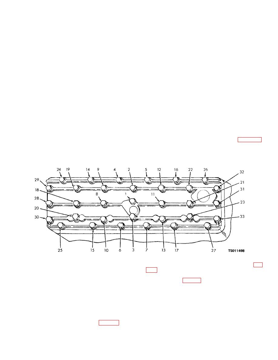
c. Installation. Using a new head gasket, install head in
solvent (Fed. Spec. P-D-680). Dry with clean, dry,
reverse order of removal. Tighten the cylinder head
compressed air.
screws according to the sequence shown in figure 4-2.
(2) Clean the top of the cylinder block with a
Torque to 35 to 40 foot-pounds (4.840 to 5.532 kgm).
scraper and a cloth dampened in cleaning solvent. Be
careful that you do not get dirt in the cylinders or water
jacket.
Figure 4-2. Cylinder head capscrew tightening sequence.
(2) Remove the valve chamber cover (7, fig.
4-4. Intake and Exhaust Valves
(3) Using a spring lifter, compress the valve
of this L-head engine are mounted in the cylinder block.
spring (5 or 10, fig. 4-3) at each valve (2 or 7) and
They are opened by operation of the camshaft through
remove the valve lock (1 or 6) from each valve that is in
adjustable valve tappets. They are closed by the valve
the closed position. Rotate the engine crankshaft to
springs. The valve stems ride in valve guides which are
close the remaining valves and remove the remaining
pressed into the block. The intake valves seat directly
locks.
in the block. The exhaust valves seat in shrink-fit valve
seat inserts in the block.
b. Removal.
(1) Remove the cylinder head (para 4-3).
4-5
|
|
Privacy Statement - Press Release - Copyright Information. - Contact Us |
