 |
|||
|
|
|||
|
Page Title:
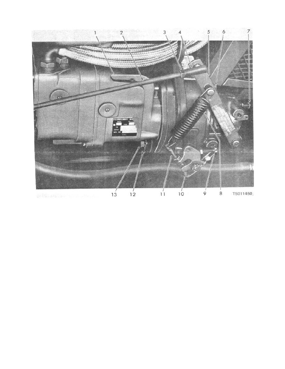
Figure 4-12. Magneto and governor installation. |
|
||
| ||||||||||
|
|
 TM 5-4320-234-12
1. Magneto
2. Throttle rod
3. Nut
4. Ball joint
5. Throttle operating lever
6. Mounting screw
7. Surge adjusting screw
8. Governor spring
9. Speed adjusting lock screw
10. Speed adjusting screw
11. Sensitivity adjusting screw
12. Ground strap
13. Mounting screw
Figure 4-12. Magneto and governor installation.
b. With the engine warmed up and with the pump
between the engine speed under load and the engine
speed without load. To broaden the range of action, use
not under load, adjust the engine idle speed to
the sensitivity adjusting screw (11). Lengthen the
approximately 150 rpm higher than the required idle
sensitivity adjusting screw to broaden the range of
speed under load. Make this adjustment by turning the
action of the engine. Compensate for speed Changes
speed adjusting screw (10). Back out speed adjusting
by readjusting the speed adjusting screw (10). To
lock screw (9) so that it will not influence the adjustment.
c. The governor's range of action is the differential
narrow the range of action, shorten the sensitivity
4-25
|
|
Privacy Statement - Press Release - Copyright Information. - Contact Us |
