 |
|||
|
|
|||
|
Page Title:
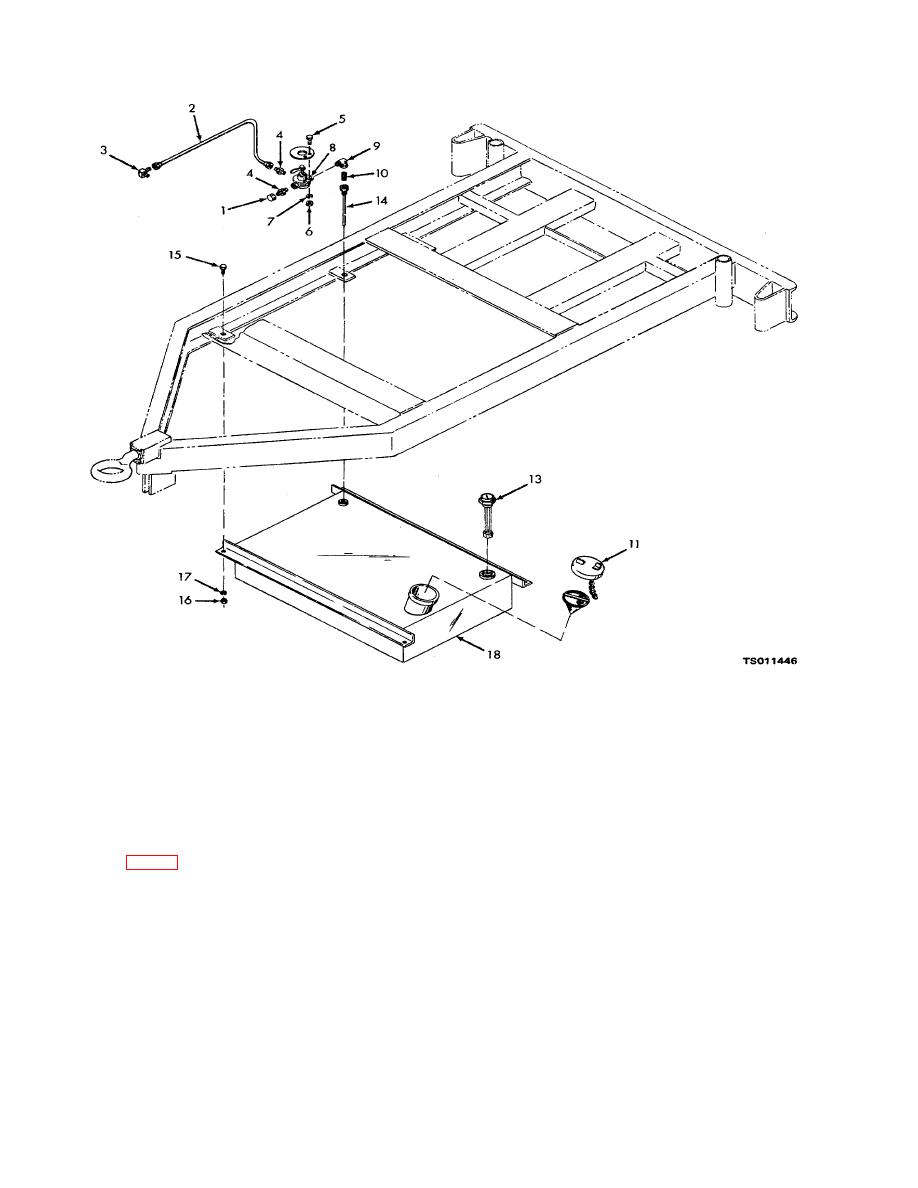
Figure 4-8. Fuel tank valve, exploded view. |
|
||
| ||||||||||
|
|
 TM 5-4320-234-12
1.
Cap
7. Lock washer
13. Fuel level gage
2.
Fuel tube
8. Fuel selector valve
14. Suction tube
3.
Tube elbow
9. Street elbow
15. Cap screw
4.
Tube adapters
10. Nipple
16. Nut
5.
Cap screw
11. Fuel tank cap
17. Lock washer
6.
Nut
12. Fuel strainer screen
18 Fuel tank
Figure 4-8. Fuel tank valve, exploded view.
KEY to fig. 4-9:
13. Fuel pump
25.
Nut
38.
Bolt
1. Fuel supply hose
14. Gasket
26.
Lock washer
39.
Flat washer
2. Elbow
15. Nut
27.
Throttle cable bracket
40.
Gasket plate
3. Elbow
16. Ball joint
28.
Carburetor
41.
Gasket
4. Pipe plug
17. Lock nut
29.
Gasket
42.
Governor
5. Carburetor bowl drain hose
18. Governor-to-carburetor
30.
Stud
43.
Gasket
6. Adapter
control rod
31.
Governor spring
44.
Cap screw
7. Carburetor drain cock
19. Ball joint
32.
Cotter pin
45.
Lock washer
8. Fuel strainer
20. Lock washer
33.
Nut
46.
Clamp
9. Elbow
21. Screw
34.
Flat washer
47.
Nut
10. Nipple
22. Nut
35.
Governor adjusting assembly
48.
Lock washer
11. Cap screw
23. Lock washer
36.
Stud
49.
Choke control cable
12. Lock washer
24. Clamp
37.
Assembled washer screw
50.
Throttle control cable
4-18
|
|
Privacy Statement - Press Release - Copyright Information. - Contact Us |
