 |
|||
|
|
|||
|
|
|||
| ||||||||||
|
|
 suction lift in excess of 25 feet.
(3) The suction line should be as large a
diameter and as short as practical, and should be
installed with as few bends as possible. Use no fittings
of less than a 6-inch diameter.
(4) The highest point in the suction line should
be at the pump, and the line should be laid in a decline
from the pump to the source. Avoid high points which
will form air pockets.
(5) Make sure that connections in the suction
line are air tight. Even a small leak will greatly reduce
pumping efficiency and may cause difficulty in priming.
(6) Support the suction line at or near the pump
to prevent strain.
d. Install the discharge line on the discharge elbow
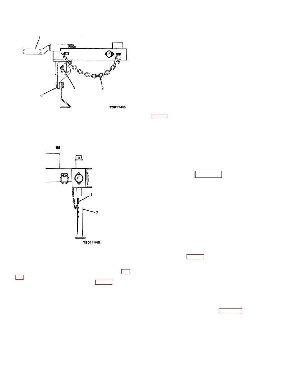
1. Tow bar
3. Lock pin
(fig. 1-1) as follows:
2. Safety chain
4. Front leg assembly
(1) Remove the threaded cap from the
discharge port. The discharge port has a 6-inch NPT
Figure 4-1. Front chassis leg.
female thread. Connect it to a discharge line with a
matching 6-inch thread.
(2) Avoid unnecessary fittings in the discharge
line. When necessary to use elbows, use long radius
type to reduce friction loss.
(3) Support the discharge line at or near the
pump to prevent strain.
WARNING
Do not operate the pump unit in an
enclosed area unless exhaust gases
are piped to the outside. Inhalation
of exhaust fumes will result in
serious illness or death.
e. If the centrifugal pump is operated indoors, you
must provide piping to carry exhaust gases to the
outside of the building. Make sure that the diameter of
the exhaust piping is large enough to prevent excessive
back pressure in the engine.
f. If an auxiliary fuel supply is to be used, connect a
1. Lock pin
2. Rear leg
fuel line between the source of supply, the auxiliary fuel
line connector (6, fig. 2-2), and the 3-way fuel source
Figure 4-2. Rear chassis stand.
selector valve (5) on the fuel tank. Operate the fuel
valve to the AUX position.
1-1), as follows:
NOTE
(1) Remove the threaded cap (fig. 1-1) from the
Due to the engine heat and vibration, engine
suction port. The suction port has a 6-inch NPT female
cylinder head bolts have a tendency to loosen at
thread. Connect it to a suction line with a matching 6-
initial operation. After the first 50 hours of
inch NPT thread.
engine use, retighten the cylinder head bolts to
(2) Keep the suction line as short as possible
a torque of 35 to 40 foot-pounds. Follow the
and the suction lift as low as possible. Reduction in
tightening sequence shown in figure 4-3.
pumping capacity becomes noticeable at suction lifts in
excess of 15 feet and is very pronounced at 25 feet.
You should not attempt to operate the pump with a
4-2
|
|
Privacy Statement - Press Release - Copyright Information. - Contact Us |
