|
| |
APPENDIX A
INSTALLATION
The following information is general in nature and is
presented as a guide to the installer and serviceman.
1.
The meter should be mounted on a suitable
base or platform so it will not be supported by
the piping, except vertical meters which are
supported directly by the piping. Dimensional
outline drawings showing size and location of
anchor holes are available for all meters.
2.
When possible, install the meter so that it
cannot be accidentally drained of product,
however, it is advisable to drain the meter of
water
and
sediment
periodically.
When
installing a meter, be sure drain plug is
accessible.
3.
Piping should not produce an undue strain on
the meter.
4.
Protect the meter and system against the
effects of thermal expansion with an adequate
relief valve.
5.
Where necessary, a deaerator or air eliminator
should be installed to keep air and vapor out of
the meter.
6.
Remove the inner mechanism if the system
is to be pressure tested with water.
7.
All piping should be internally clean before
meter is put into operation. Rust, dirt, welding
shot and other foreign material should not be
present. It is best to remove the inner
mechanism and flush the lines. This will
prevent damaging the metering element. The
meter should be protected by a strainer.
8.
Do not calibrate with water or allow water to
stand in the meter. Flush meter with a light
lubricating oil if it is left idle or stored.
9.
Unless otherwise specified, meters normally
flow from left to right when viewing from the
flanged side of the housing. Most meters can
be changed to flow from right to left, see
REVERSING SECTION.
10.
A counter may be located in any one of four 90
positions. Large numeral counters may be
located in any of eight 45 positions.
OPERATION
START-UP
It is best to fill the meter by gravity. However,
where hydraulic conditions require that the pump(s)
be operated, extreme care should be used in
opening the valves at the meter. In all instances,
the air should be evacuated slowly from the meter
and system.
1. Establish product flow through meter .
With outlet valve closed, slowly open inlet
valve. Slowly open outlet valve until counter
begins to turn. Leave outlet valve in throttled
position until air is evacuated from meter. This
is necessary to protect meter from excessive
speeds due to air in lines of system.
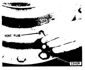
2.
Loosen vent plug when meter is filled with
liquid, Fig. 3 (On meters so equipped).
Permit the air trapped in the meter cover to
escape through the threads. Close plug when
product begins to seep through the threads.
FIGURE 3 - LOOSENING VENT PLUG
3.
To fully open inlet and outlet valves, open
valves slowly, pausing if register operation is
rough. Continue opening when operation
becomes smooth.
A9-35
|