|
| |
DISASSEMBLY
First remove the counter and counter adapter. Next
remove the outer cover, this exposes the inner
mechanism.
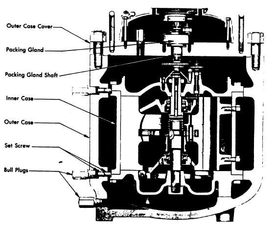
The inner mechanism of the Double Case Meter is held
in position by Allen Head Set Screws which are under
the two Bull Plugs shown in Figure 14.
Each hole contains two Allen Head Set Screws and it is
recommended that both be completely re
moved from the outer housing. The purpose of this is to
enable the inner mechanism to be properly positioned
when reinstalled. The inner mechanism will be found to
show the marks of these set screws and these marks
can be used to line up the inner mechanism properly
when being replaced in the outer housing.
After removing inner mechanism from outer housing
proceed with disassembly, inspection and reassembly as
outlined in Section on Single Case Meters.
FIG. 14. CONSTRUCTION OR TYPICAL HIGH PRESSURE METER.
NOTE
DOUBLE CASE METERS NOTE SUPPLIED.
MAINTENENANCE PROCEDURES INCLUDED
FOR REFERENCE ONLY.
A9-26
|