|
| |
SINGLE CASE METER:
DISMANTLING AND INSPECTION
First remove the counter and the counter adapter. This
exposes the gear train. (Important Note: For Temperature
Corrected Meters, see Page 12.) Visual inspection of the
gears and gear shafts will determine the need for
replacement. On S-13 and "T" meters the calibrator must
be removed to reveal the gear train.
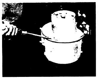
FIG. 5. COVER OF SMALLER METERS IS REMOVED
BY PRYING WITH A SCREWDRIVER.
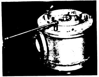
FIG. 6. JACKSCREWS (COVER SCREWS) ARE USED
TO BREAK SEAL AND LIFT COVER OF
LARGER METERS.
Next, remove the adjusting screw cap on meters so
equipped. IMPORTANT: Do not attempt to remove the
meter housing cover before removing the adjusting
screw cap, the rotor shaft nut and shaft collar. Failure
to remove the upper shaft nut at this point will result in
breakage of the meter cover or base. To remove the
meter cover, pry evenly around its perimeter using the
slots provided for this purpose. Covers on larger
meters are provided with three tapped holes. Three
cover bolts may be screwed into these holes to raise
the cover evenly. ( See Figures 5 & 6 ).
After the meter cover is removed, any liquid still
remaining in the meter should be drained or otherwise
eliminated. If the meter is in service on crude oil or any
other viscous liquid, a solvent should be used to
dissolve the residue.
Bottoming of rotor assemblies is done to provide a firm
support for the assembly in order to determine whether
clearances in the meter are within the proper
tolerances. There is a clearance chart on the bottom of
Page 7 showing maximum and minimum allowable
tolerances for meters operating up to 150°F and
viscosities less than 5,000 SSU. (For clearances above
150F., consult your nearest Smith Meter Sales Office.)
In the case of meters shown in Figure.2, on Page 2, the
rotor is bottomed in the meter housing by turning the
adjusting screw located in the base of the meter. For
meters shown in Figure 3, on Page 3, the rotor is
bottomed
by
first
removing
the
complete
rotor
assembly, then removing the shaft spring which is
located in the shaft socket in the base of the meter.
When the rotor assembly is reinstalled without the
spring it will rest on the bottom of the housing. For
meters shown in Figure 4, on Page 3, the rotor
assembly may be bottomed by turning the adjusting
screw in the top of the rotor shaft.
A9-21
|