|
| |
TM 07661B-14/1
APPENDIX A
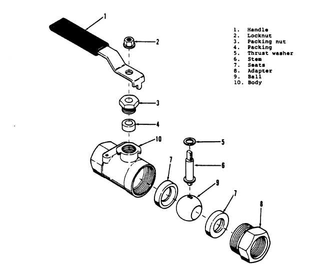
Figure A 3-21. Purge And Charge Valve Assembly
(2)
Install a new seat (7) into valve bore, chamfer toward ball. Insert ball (9) into valve body, engaging groove
on outer circumference of ball with flats on bottom of valve stem. Install a new seat (7), chamfer toward ball, seating it
firmly against ball.
(3)
Coat threads of adapter (8) with Loctite 271 (red). Install adapter (8) and tighten securely.
(4)
Carefully install new packing (4) into threaded bore for valve stem on side of valve body.
(5)
Install packing nut (3) over valve stem and into threaded bore. Tighten packing nut securely.
(6)
Install handle (1) on stem, positioning as in original installation, and secure with locknut (2).
A 3-45
|