|
| |
TM 10-6630-247-13&P
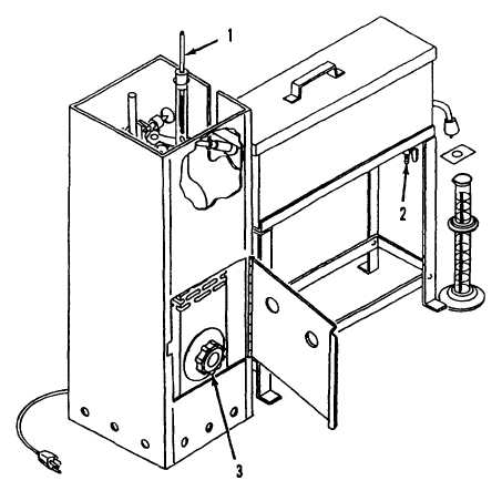
2-2. DISTILLATION UNIT CONTROLS AND INDICATORS.
Thermometer (1)
Indicates temperature of test sample in the distillation flask.
Drain Valve (2)
A hand operated drain valve is located on the bottom of the condenser assembly. The purpose of the
valve is to drain coolant from the condenser tank. Turning the control handle in line with the valve
body opens the valve. Turning the control handle out from the valve body closes the valve.
Heater Control Knob (3)
The distillation unit heater is operated by a control knob mounted on the face of the heater. Turning
the knob to the right increases heater output, turning the knob to left decreases output. Heater output
ranges from 0 to 750 watts. Indicator marks on the control knob reflect the percentage of heater
output. For example, turning control knob to 50 means that heater output is 50% of capacity , or 375
watts.
Figure 2-2. Distillation Unit Controls and Indicators.
2-3
|