|
| |
TM 10-5430-242-12&P
0031 00
0031 00-1/2 blank
OPERATOR AND UNIT MAINTENANCE MANUAL
(INCLUDING REPAIR PARTS AND SPECIAL TOOLS LIST)
COLLAPSIBLE FABRIC TANKS, FUEL STORAGE,
10,000 AND 20,000 GALLON
BERM LINER DRAIN HOSE ASSEMBLY
SERVICE AND REPAIR
INITIAL SETUP
Materials/Parts
Equipment Condition
Detergent
Berm liner drain ball valve removed
(Item 6, WP 0042 00
(WP 0023 00)
Dry Cleaning Solvent
(Item 7, WP 0042 00)
Rags, Wiping
(Item 2, WP 0042 00)
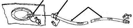
SERVICE
1. Pull outward on cam-lever arms (1) and remove berm liner drain hose assembly (2) from male
disconnect coupling (3).
2. Flush berm liner drain hose assembly (2) with hot, soapy water.
3. Rinse out berm liner drain hose assembly (2) thoroughly and air dry.
WARNING
Dry cleaning solvent, A-A-59601, used to clean parts, is potentially dangerous to
personnel and property. It produces toxic and flammable fumes. Use only in well
ventilated areas. Avoid repeated and prolonged skin contact. Do not use solvent
near an open flame or near excessive heat. The flash point of the solvent is 100F
to 130F (38 C to 59 C).
CAUTION
Dry cleaning solvent, A-A-59601, used to clean parts, must not come into contact
with any part of the fuel tank fabric. Damage to the fabric will occur.
4. Clean the end of male disconnect coupling (3) with dry cleaning solvent and dry thoroughly with rags.
5. Inspect berm liner drain hose assembly (2) for cracks, tears or wear.
6. Push berm liner drain hose assembly (2) on male disconnect coupling (3). Push inward on cam-lever
arms (1) and lock berm liner drain hose assembly (2) in place.
7. Install the berm liner drain ball valve. See WP 0023 00.
END OF WORK PACKAGE
1
2
3
|