|
| |
TM 10-5430-232-12&P
NOTE
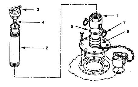
Normally the vent pipe and female coupling half will be received
preassembled.
(h) Check to see that relief cap (3) operates freely.
(i) Check to see that flame arrestor (4) is installed.
(j) Check to see that relief cap (3) is installed tightly on vent pipe (2).
(k) Check to see that gasket (5) is in place and correctly seated.
(I) Insert female coupling half (1) over flanged adapter (6) with cam-lever arms (7) in outward
position.
(m) Press cm-lever arms (7) upward and inward to lock vent pipe assembly into operating
position.
(n) Connect filler/discharge elbows to tank. Close both cam arms on each assembly at the same
time by hand.
(o) Select one filler/discharge elbow to be used in operation. Place dust cap or plug on the
filler/discharge elbow that will not be used.
(p) Connect hose to elbow. Close both cam arms at the same time by hand.
(q) Connect valve to hose. Close both cam arms at the same time by hand.
(r) Close the gate valve.
Figure 4-6. Vent and pipe assembly
4-8
|