|
| |
TM 10-4930-250-13&P
NOTE
Do notopenelbowvalvecouplings.
f.
Install the elbow valve (2) couplings on the inlets and outlets of all four fuel drums.
NOTE
Whenever coupling together unisex couplings, depress continuity ball and observe that ball
pops back out. Failure to check or failure of ball to pop back out could allow the buildup
of static electric charge that could cause an explosion and death.
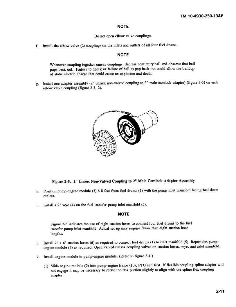
g.
Install one adapter assembly (2" unisex non-valved coupling to 2" male camlock adapter) (figure 2-5) on each
elbow valve coupling (figure 2-3, 2).
Figure 2-5. 2" Unisex Non-Valved Coupling to 2" Male Camlock Adapter Assembly
h.
Position pump-engine module (3) 6-8 feet from fuel drums (1) with the pump inlet manifold facing fuel drum
outlets.
i.
Install a 2" wye (4) on the fuel transfer pump inlet manifold (5).
NOTE
Figure 2-3 indicates the use of eight suction hosesto connect four fuel drums to the fuel
transfer pump inlet manifold. Actual set up may require fewer than eight suction hose
lengths.
j.
Install 2" x 6' suction hoses (6) as required to connect fuel drums (1) to inlet manifold (5). Reposition pump-
engine module (3) as required. Open valved unisex coupling valves on suction hoses, wye, and inlet manifold.
k.
Install engine module in pump-engine module. (Refer to figure 2-4.)
(1) Slide engine module (9) into pump-engine frame (10), PTO end first. If flexible coupling spline adapter will
not engage it may be necessary to rotate the flex portion slightly to align with the spline flex coupling
adapter.
2-11
|